Model aviation, technology, and other stuff
Here are some things that I’ve worked on or thought about. Most of this expresses my love of aviation, love of coding, and love of puzzling through tricky problems. Maybe something here will be interesting, helpful, or spark further thought someday. Most of the code described in these posts can be found on github.
-
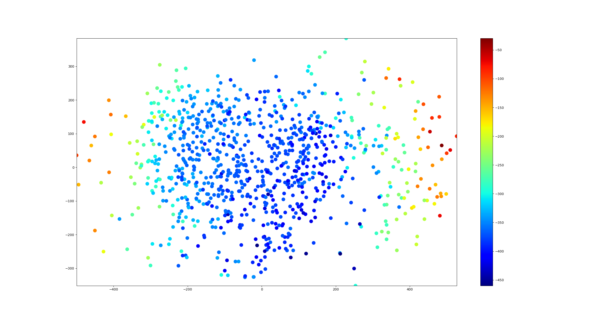
Dynamic Mode Decomposition Fundamentals
Fundamentals of Dynamic Mode Decomposition (DMD)
-
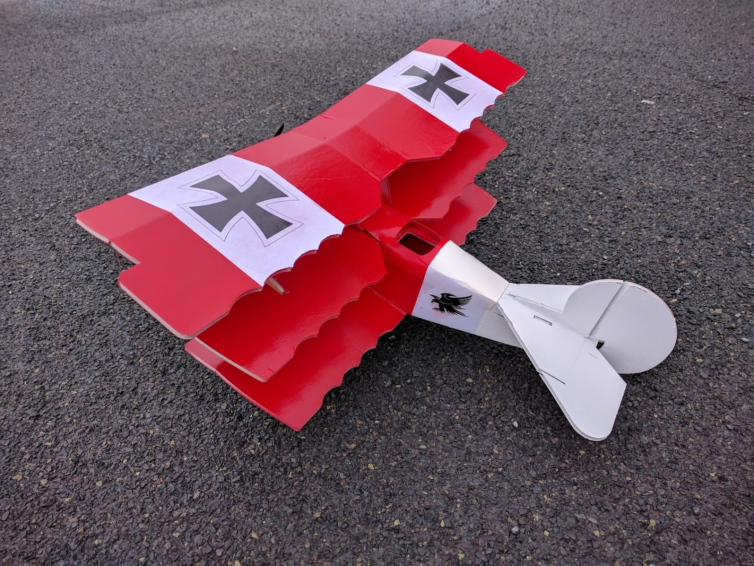
Flitetest DR1 Triplane
-
Simplicity in UAS Flight Controller Design
Simplicity is an important design goal. I wrote a different post explaining why. How might this principle beconsidered when design a complex system like a UAS autopilot.
-
Simplicity in Design
This is the main point of this post: Simplicity is an important design goal that is often overlooked.
-
Camera as a sensor
Horizon tracking and constructing a virtual gyro.
-
Virtual Choir Maker
There is nothing more magical and wonderful than when our voices unite.
-
Faith, Music, and Politics
The songs we sing
-
Simple Vignette Correction
From wikipedia: In photography and optics, vignetting is a reduction of an image’s brightness or saturation toward the periphery compared to the image center.
-
DJI Phantom 4 Pro camera vs. Sony A6000
Recently I flew a DJI Phantom 4 Pro v2 head to head with an in-house (U of MN AEM UAS Lab) developed fixed wing UAS. This comparison isn’t entirely apples to apples, but maybe someone will find it useful.
-
Almost, but not entirely real-time process control with Linux.
First, if you are interested in doing real time process control on Linux, go watch this awesome presentation. This is way more important than reading my post! Do it now!
-
New Hardware Design Project
Feb 11, 2018 update: After some amount of tearing my hair out and some help from the beaglebone IRC community, I have the pocketbeagle UART2 configured and working to my external connector. Telemetry is up and running! I also plugged in an SBUS receiver, verified it is getting power correctly, bound it to my transmitter, and then verified the system is seeing my pilot inputs correctly. Next up: verifying all 8 pwm output channels.
-
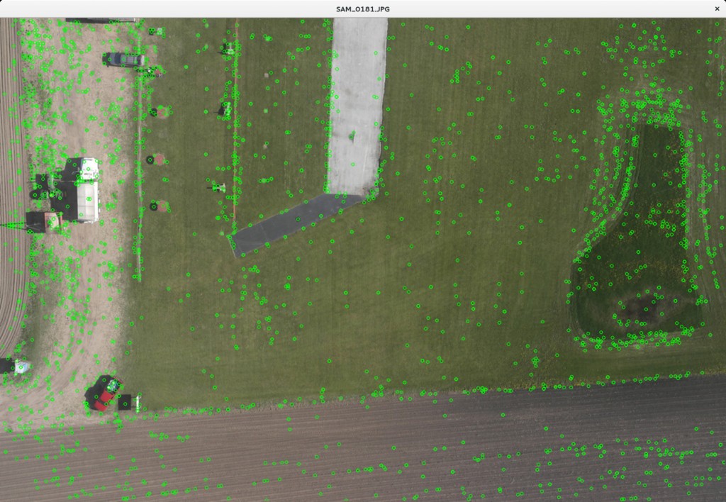
Adventures in Aerial Image Stitching Episode #7
-
Adventures in Aerial Image Stitching Episode #6
Generating survey area coverage routes
-
Celebrating the 4000th git commit!

-
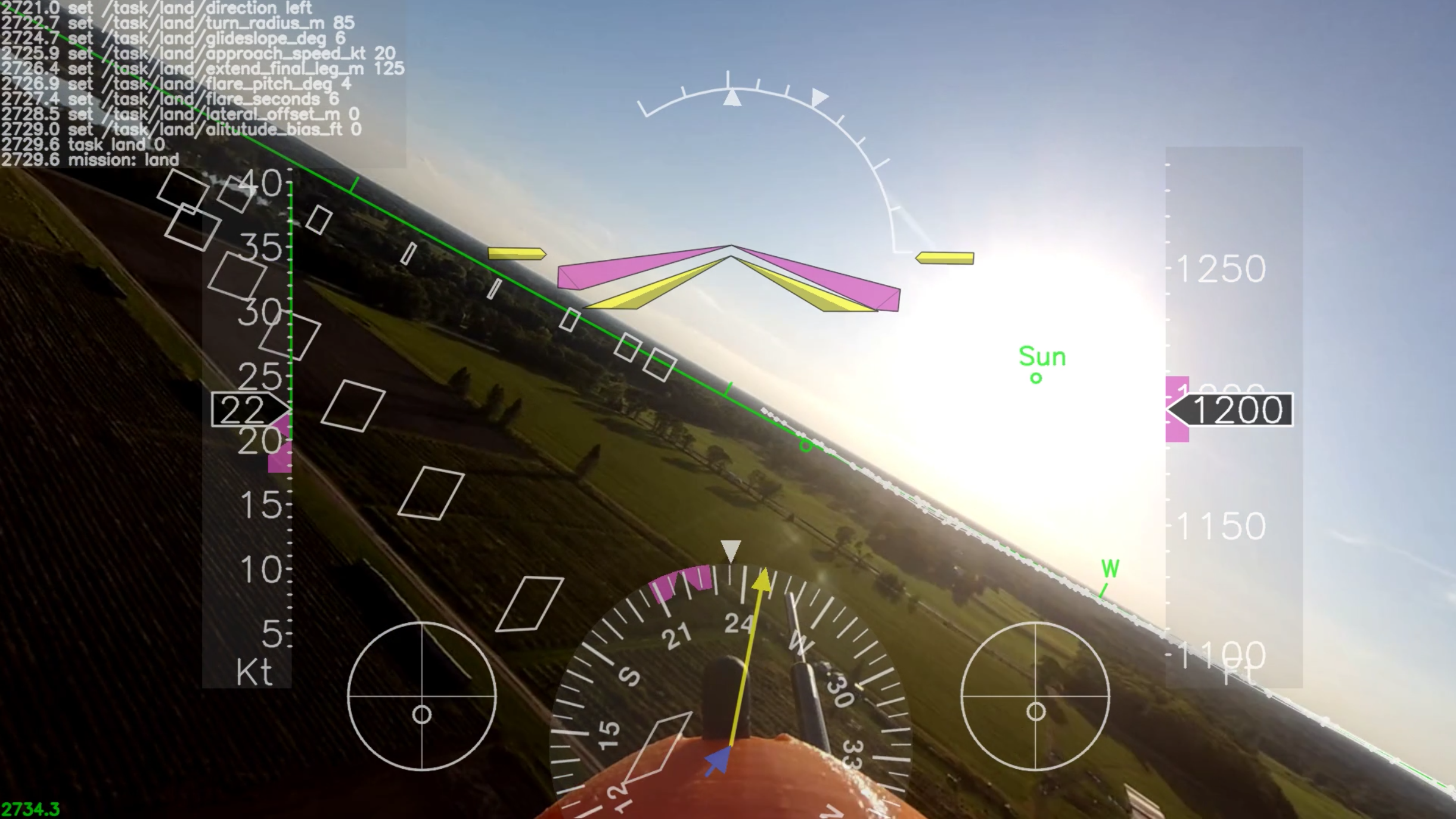
Aerial Survey Flight (with Augmented Reality)
Basic Details
-
Spin Testing
Wikipedia Spins: In aviation’s early days, spins were poorly understood and often fatal. Proper recovery procedures were unknown, and a pilot’s instinct to pull back on the stick served only to make a spin worse. Because of this, the spin earned a reputation as an unpredictable danger that might snatch an aviator’s life at any time, and against which there was no defense._
-
Sunset Flight
This is Skywalker Flight #74, flown on Sept. 7, 2017. It ended up being a 38.5 minute flight–scheduled to land right at sunset. The purpose of the flight was to carry insect traps at 300′ AGL and collect samples of what might be flying up at that altitude.
-
Field Comparison of MPU6000 vs VN100T
The U of MN UAV Lab has flown a variety of sensors in aircraft, ranging from the lowly MPU-6000 (such as is found on an atmel based APM2 board) all the way up to an expensive temperature calibrated VectorNAV VN-100T. I wish to present a quick field comparison of these two sensors.
-
Drosophila-nator (Prototype)
This is a joint Entomology / Aerospace project to look for evidence that Spotted Wing Drosophila (an invasive species to North America) may be migrating at higher altitudes where wind currents can carry them further and faster than otherwise expected.
-
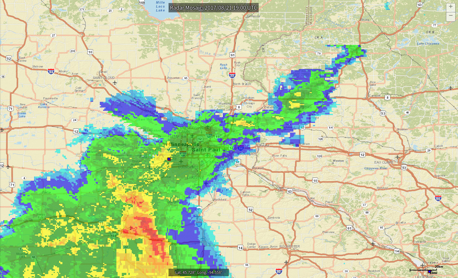
Flying on the Edge of a Storm
-
Flying on the Edge of an Eclipse (2017)
 Photo credit: Doug Olson
 -
Adventures in Aerial Image Stitching Episode #5
Last Friday I flew an aerial photography test flight using a Skywalker 1900 and a Sony A6000 camera (with 20mm lens.) On final approach we noticed a pair of deer crossing under the airplane. I went back through the image set to see if I could spot the deer in any of the pictures. I found at least one deer in 5 different shots. Here are the zoom/crops:
-
Continuously Self Calibrating UAV Compass

-
Autopilot Visualization: Flight Track
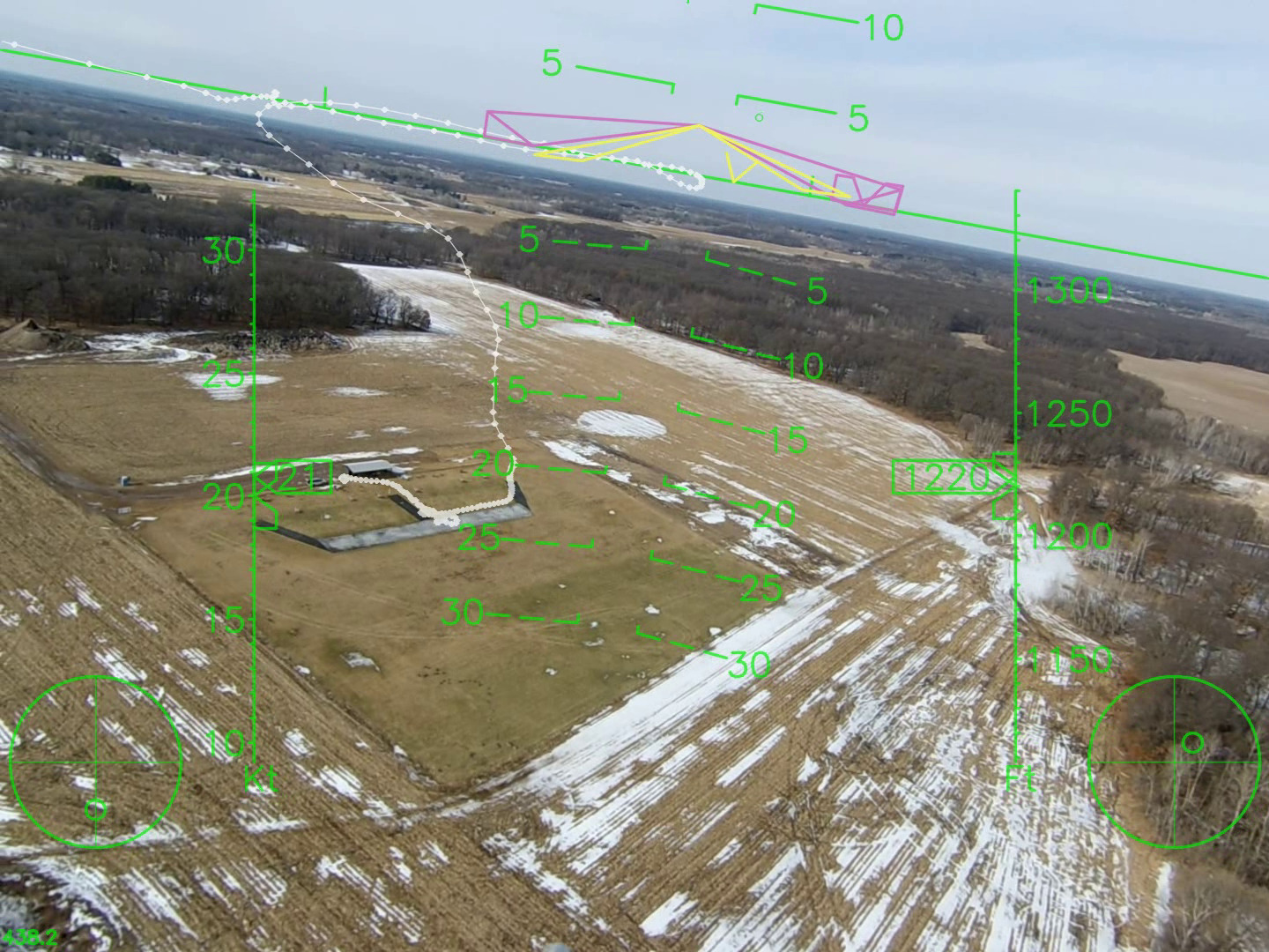 Circling back around to see our pre-flight, launch, and climb-out trajectory.
 -
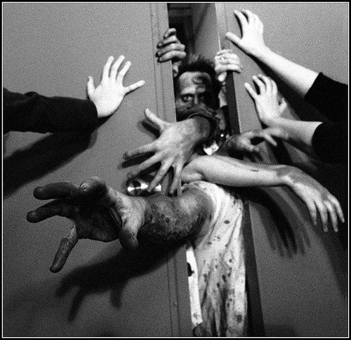
Zombie Door
-
Failure is not fatal

-
Synthetic Air Data (an afternoon hack)
 Air France #447
 -
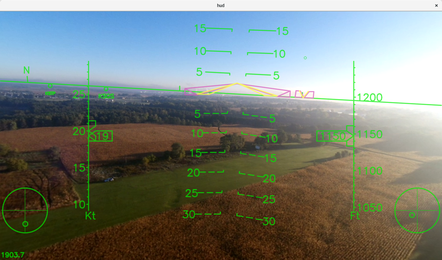
Howto: Action Cam HUD overlay
In this post I share my process and tools for creating HUD overlays on a flight video. Here is a quick overview of the process: (1) Calibrate your camera, (2) Extract the roll rate information from the flight video, (3) Automatically and perfectly time correlate the video with the flight data, (4) Render a new video with the HUD overlay.
-
Autopilot Visualization
-
Mistakes!


-
Automated Movie Frame Extracting and Geotagging
This is a short tutorial on an automated method to extract and geotag movie frames. One specific use case is that you have just flown a survey with your quad copter using a 2-axis gimbal pointing straight down, and a gopro action cam in movie mode. Now you’d like to create a stitched map from your data using tools like pix4d or agisoft.
-
Image Stitching Tutorial Part #2: Direct Georeferencing
What is Direct Georeferencing?
-
Image Stitching Tutorial Part #1: Introduction
-
Flight Milestones
Congratulations!
-
APM2 Sensor Head
-
PBY Catalina
January 27, 2015
-
Sonic 64
Hobbyking Sonic 64
-
Polaris Ultra
Manufacturer: Model Aero
-
Coding and Complexity
Norris Numbers
-
Cutting the Cord
Update: 10/01/2014
-
Adventures in Aerial Image Stitching
A small UAV + a camera = aerial pictures.
-
Smart Trainer Photo Shoot
Design Observations
-
Aerosky 185 Photo Shoot
-
Aerosky 185 Build Notes
I was interested in the Aerosky Sky Trainer 185 because it looks a lot like a Cessna 185. It has the 185 tail and is setup as a taildragger. Technically the rear window is not correct for a 185, but there are a lot of things you could nitpick if you really wanted to go there. The other interesting aspect of this kit is that it includes a full set of float for water operations. I live near a little lake so I am hoping this will fly well off water on a nice calm summer evening.
-
Build Your Own PC (2014 Edition)
The World is Constantly Changing
-
Wisconsin Dells

-
BackupPC, LVM, Cloning and Resizing Drives
I recently went through the process of trying to move my entire 1.5 Tb BackupPC tree to a new drive. Here are some thoughts and comments from that experience.
-
Spiraling Under Control
One of the staples of fixed wing autopilots is the circle hold. A circle hold is the closest thing you can get to a pause button with a vehicle that must be in constant forward motion to stay aloft. There are a few hidden challenges in the task, including wind compensation and some unexpected coupling that can lead to weird looking oscillations if not handled well. People have been doing circle holds with UAV’s for a long long time, so I don’t bring anything new to the table, but it is always fun to play, err I mean experiment.
-
RC Aircraft Precision Balancer and Work Stand
This morning I whipped together a “precision aircraft balancer” (like the Great Planes “C.G. Machine”.) I built it out of $5.57 worth of PVC pipe and connectors from Fleet Farm and it probably took me an hour at the most.
-
Sold the P-47
I sold my P-47 on craigslist today. I liked it, but for whatever reason, it wasn’t my favorite to fly and I’ve got my eye on something else … but I need to free up some space first … ! I really enjoy flying my PBY though … I need to set up a category and post a few pictures of that soon!
-
“fedup” with Fedora!
Fedora 18 “Spherical Cow”
-
Python Airfoil Manipulation Library
-
I’m Thankful for my Senior Telemaster
This Thanksgiving day I’m thankful for many blessings: family, friends, neighbors, shelter, food, our siberian husky who lived 16 years, and many other things. The weather was nice Thanksgiving morning so I was thankful to have an hour to run out to the field first thing to do some flying.
-
Setting up “autologin” on a gumstix running the 3.5 kernel (yocto, poky, et. al.)
The gumstix.org wiki has a page on how to configure your gumstix to auto-login on boot. This can be very nice for “production” systems where the intention is to power on and run some specific firmware/code every time.
-
Hacking the APM2 Part #5: Flight Testing
-
Hacking the APM2 Part #4: Laying out a 'hybrid' system
Imagine for one second that you are a UAV developer. The DIYdrones ArduPilot is an awesome piece of hardware; you love all the great sensors that are attached; you love the all-in-one design and the small/light size. But you are also feeling the limits of it’s ATMega 2560 processor and the limits of it’s 256Kb of RAM. And maybe, you enjoy developing code within a full blown Linux developers environment with all the supporting libraries and device drivers that Linux has to offer.
-
Hacking the APM2 Part #3: Servos

-
Hacking the APM2 Part #2: Fun with Baud Rates
The autopilot architecture I am building involves and APM2 collecting all the sensor data and sending it over a serial connection to a Gumstix Overo running Linux, and then in return the Overo sends servo commands back to the APM2. As you can guess, this turns out to be quite a bit of data being sent at a high rate. If all the processing, filtering, and computation is being done on the Overo it is important to have a high update rate, low latency, reliable communication, and no major pauses in processing at either end.
-
Hacking the APM2 Part #1: Introduction

-
More wing related repairs
I encountered two more issues that I needed to address:
-
Android Tablets
What is the ultimate computing device?
-
Seat of the Pants Engineering: I Need More Power!
One of the challenges of bread boarding is finding the right voltage sources and ground pins to power and connect a variety of components. Recently I was faced with the challenge of connecting a Gumstix Overo with 1.8V TTL signals to a VectorNav VN-100T IMU with 3.3V TTL signals via SPI. I just happened to have 2 Sparkfun logic level converters on hand.
-
Oh no! Fedora 16!
Day 1
-
Wifi versus Powerline Networking
The Problem
-
How to be an Electronics Whiz on a Small Budget
Simple tools that you will use all the time!
-
Resolution 3: Design Evolution to First Flight
Here is a photo blog showing the progress from initial rough prototype, to final design, to mold making, to test flying the first production aircraft:
-
Gumstix Overo, RC Servos, and PWM Signal Generation
What I want to do: Control RC Servos from a Gumstix Overo
-
Fedora 15 and Gnome 3
This weekend I took the plunge into Fedora 15 with Gnome 3. This is a major change from previous versions of Fedora.
-
P-47 Wing Repair

-
Visualizing Circle Holds
-
Better FlightGear Smoke
Overview
-
Charles Moore on ABC
Update: 2020, November 15 - Sadly this video is no longer avaible, but I’m sure if you search youtube or google you can find a ton of similar content.
-
The Coolest Thing *EVER*
Formation RC Flying
-
Building Openembedded for Overo on Fedora 14
[
 ](https://gallinazo.flightgear.org/images/2011/04/overo-mb.jpg)
-
North Pacific Ocean Sunsets
-
North Pacific Debris Gallery
NOAA Debris Research Cruise
-
Tracking Ocean Debris in the North Pacific

-
Seawind Photo Shoot
Great Planes Seawind EP
-
Launching Update
Update on MiG-15 Launching Technique
-
Hobby Lobby P-47
Introduction
-
Build Your Own Freaking Fast FlightGear PC
Building your own PC
-
Real-time UAS Simulation and Visualization
Real-time UAS Simulation and Visualization
-
3D Modelling with MoI
3D Modelling with MoI
-
Physics Modelling
Dynamics (Physics) Modelling and Flight Simulation
-
3D Modelling … with … Perl?!?
3D modeling with perl?!? What the…? Huh?!?
-
Google Nexus S

-
Shadow Cam
-
ATI Command Augmentation System
ATI Command Augmentation System #1
-
ATI SAS #2
Senior Telemaster SAS Test Day #2
-
Telemaster SAS
Senior Telemaster SAS Test Flight #1
-
Elevator Gain Tuning
Tuning UAV Autopilots
-
Commercial Systems Versus Research
Comments on the use of commercial hardware or software in a university research context.
-
Hobby-Lobby MiG-15 Electric Ducted Fan Jet
Assembly
-
Great Planes Seawind EP
Great Planes Seawind EP (Rx-R)
-
Shrike 40 ARF
Lanier Shrike 40 ARF
-
Great Planes Big Stick 40
-
Midwest Citabria
Midwest Citabria
-
Flying
EGN-1 Flight Testing
-
Senior Telemaster
Airframe Todo List
-
Unicorn
UAV Research at the University of Minnesota
-
Rascal C
Sig Rascal C, 49″ Wing Span, HiMax Outrunner Upgrade
-
Ultra Sport 40 ARF Flying
Great Planes Ultra Sport 40 ARF (Red)
-
Senior Telemaster Early Flights
While rummaging around my hard drive I stumbled on some early footage of our Senior Telemaster flying. This footage includes some of my earliest successful autonomous flight using the original MNAV sensor head (now discontinued.) There isn’t anything especially great about this footage, other than I love the way the Telemaster looks in the air, especially it’s “scale” take offs and landings. These videos date back to sometime in mid-summer 2007.
-
Sig Rascal 110 #1 Instrumentation
MicroGear and the Xbow MNAV
-
Maintenance Log
Lanier Mariner Maintenance Log
-
Mariner Snow Flying
Lanier Mariner Snow Flying
-
Piper Cub Photo Shoot (Floats)
Photo shoot from my maiden flight off floats.
-
Mariner 40 Water Flying
Lanier Mariner Water Flying
-
Sig Rascal 110 #2 Results
Sig Rascal 110 #2 – UMN UAV Project
-
Sig Rascal 110 #1 Rebuild
Sig Rascal 110 #1 - UMN UAV Project
-
Sig Four Star 40
Sig Four Star 40
-
Piper Cub Photo Shoot (Wheels)
Photo shoot from my maiden flight off wheels.
-
Hangar 9 Piper Cub
Hangar 9 Piper Cub Ultra Series (ARF) w/ Floats
-
Thunder Tiger Tiger Bipe 40
Thunder Tiger Tiger Bipe 40
-
Aerobird Challenger
Hobbyzone Aerobird Challenger
-
Sig Rascal 110 #1 Flying
Sig Rascal 110 #1 – UMN UAV Project
-
Sig Rascal 110 #1 Construction
Sig Rascal 110 #1 – UMN UAV Project
-
Stabilization
Roll/Pitch Stabilization System
-
Overview
EGN Project Overview
-
Construction
EGN Construction Log
-
Super Sportster Mk I ARF
Super Sportster 40 Mk-I (ARF)
-
Ace High Mk-II
Ace High Mk-II
-
Mariner Construction
Lanier Mariner 40 ARF (Orange)
-
Ultra Sport 40 Assembly
Great Planes Ultra Sport 40 ARF (Red)
-
Midwest Sweet Stik
Midwest Sweet Stik Pictures
-
Fairchild F-24
Guillow’s Fairchild F-24 Project
-
Sig Kadet Mk II
Sig Kadet Mk II
-
Sig Kadet Mk I
Sig Kadet Mk I
-
Pre-RC
Earlier Model Airplanes


 ](https://gallinazo.flightgear.org/images/2011/04/overo-mb.jpg)