Synthetic Air Data (an afternoon hack)
 Air France #447
Motivation
On June 1, 2009 Air France flight #447 disappeared over the Atlantic Ocean. The subsequent investigation concluded “that the aircraft crashed after temporary inconsistencies between the airspeed measurements – likely due to the aircraft’s pitot tubes being obstructed by ice crystals – caused the autopilot to disconnect, after which the crew reacted incorrectly and ultimately caused the aircraft to enter an aerodynamic stall from which it did not recover.” https://en.wikipedia.org/wiki/Air_France_Flight_447
This incident along with a wide variety of in-flight pitot tube problems across the aviation world have led the industry to be interested in so called “synthetic airspeed” sensors. In other words, is it possible to estimate the aircraft’s airspeed by using a combination of other sensors and techniques when we are unable to directly measure airspeed with a pitot tube?
Basic Aerodynamics
Next, I need to say a quick word about basic aerodynamics with much hand waving. If we fix the elevator position of an aircraft, fix the throttle position, and hold a level (or fixed) bank angle, the aircraft will typically respond with a slowly damped phugoid and eventually settle out at some ‘trimmed’ airspeed.
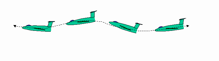
If the current airspeed is faster than the trimmed airspeed, the aircraft will have a positive pitch up rate which will lead to a reduction in airspeed. If the airspeed is slower than the trimmed airspeed, the aircraft will have a negative pitch rate which will lead to an acceleration. https://en.wikipedia.org/wiki/Phugoid
The important point is that these variables are somehow all interrelated. If you hold everything else fixed, there is a distinct relationship between airspeed and pitch rate, but this relationship is highly dependent on the current position of elevator, possibly throttle, and bank angle.
Measurement Variables and Sensors
In a small UAS under normal operating conditions, we can measure a variety of variables with fairly good accuracy. The variables that I wish to consider for this synthetic airspeed experiment are: bank angle, throttle position, elevator position, pitch rate, and indicated airspeed.
We can conduct a flight and record a time history of all these variables. We presume that they have some fixed relationship based on the physics and flight qualities of the specific aircraft in it’s current configuration.
It would be possible to imagine some well crafted physics based equation that expressed the true relationship between these variables …. but this is a quick afternoon hack and that would require too much time and too much thinking!
Radial Basis Functions
Enter radial basis functions. You can read all about them here: https://en.wikipedia.org/wiki/Radial_basis_function
From a practical perspective, I don’t really need to understand how radial basis functions work. I can simply write a python script that imports the scipy.interpolate.Rbf module and just use it like a black box. After that, I might be tempted to write a blog post, reference radial basis functions, link to wikipedia, and try to sound really smart!
Training the Interpolater
Step one is to dump the time history of these 5 selected variables into the Rbf module so it can do it’s magic. There is a slight catch, however. Internally the rbf module creates an x by x matrix where x is the number of samples you provide. With just a few minutes of data you can quickly blow up all the memory on your PC. As a work around I split the entire range of all the variables into bins of size n. In this case I have 4 independent variables (bank angle, throttle position, elevator position, and pitch rate) which leads to an n x n x n x n matrix. For dimensions in the range of 10-25 this is quite manageable.
Each element of the 4 dimensional matrix becomes a bin that holds he average airspeed for all the measurements that fall within that bin. This matrix is sparse, so I can extract just the non-zero bins (where we have measurement data) and pass that to the Rbf module. This accomplishes two nice results: (1) reduces the memory requirements to something that is manageable, and (2) averages out the individual noisy airspeed measurements.
Testing the Interpolater
Now comes the big moment! In flight we can still sense bank angle, throttle position, elevator position, and pitch rate. Can we feed these into the Rbf interpolater and get back out an accurate estimate of the airspeed?
Here is an example of one flight that shows this technique actually can produce some sensible results. Would this be close enough (with some smoothing) to safely navigate an aircraft through the sky in the event of a pitot tube failure? Could this be used to detect pitot tube failures? Would this allow the pitot tube to be completely removed (after the interpolater is trained of course)?
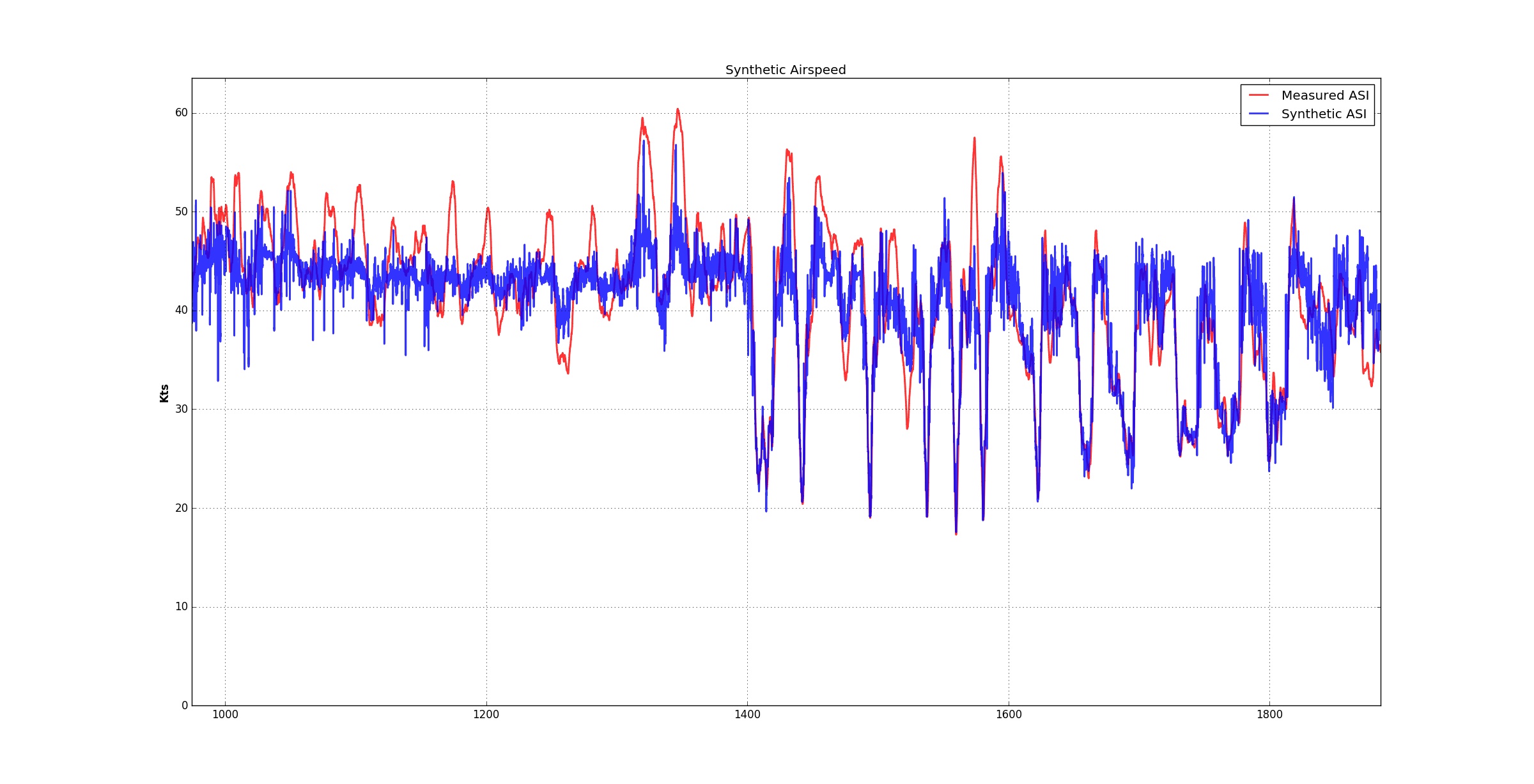
Synthetic airspeed estimate versus measured airspeed.
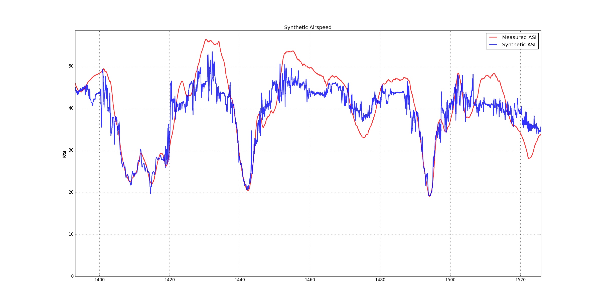
Zoom on one portion of the flight.
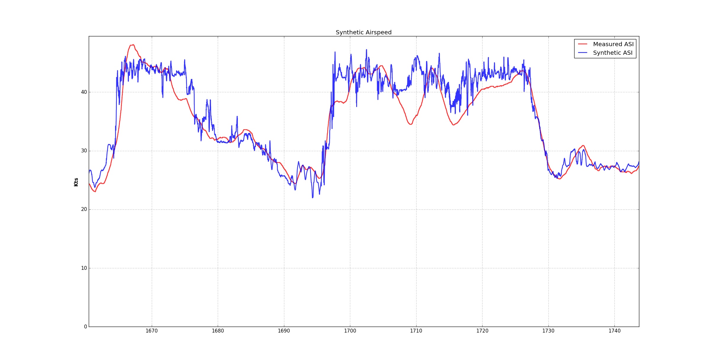
Zoom in on another portion of the flight.
Source Code
The source code for this experimental afternoon hack can be found here (along with quite a bit of companion code to estimate aircraft attitude and winds via a variety of algorithms.)
https://github.com/AuraUAS/navigation/blob/master/scripts/synth_asi.py
Conclusions
This is the results of a quick afternoon experiment. Hopefully I have showed that creating a useful synthetic airspeed sensor is possible. There are many other (probably better) ways a synthetic air speed sensor could be derived and implemented. Are there other important flight variables that should be considered? How would you create an equation that models the physical relationship between these sensor variables? What are your thoughts?