Construction
EGN Construction Log
img_2376 Please note: these entries are arranged in reverse chronological order with the newest entries at the top.
Maintanence Tasks
- Engine installation. <ul type="circle">
- Need to enlarge the cowl openings a bit for better engine access.
</ul>
- Radio installation. <ul type="circle">
- Need to fashion better strain relief for the antenna where it exits the fuselage.
</ul>
- Apply decals.
May 13, 2005.
This project is officially moved over to active flight status!
May 11, 2005.
Today I threw on about 10.5 oz of lead up front to balance the airplane. I think we are just about ready to top off the batteries and go fly!
May 9, 2005.
Sealed gap (on one side) between horizontal stabalizer and fuselage. Balancing: now that pretty much everything is in place, I have done some initial test balancing. I have 4 3/4 oz of stick on lead in my inventory, but I think I will need a bit more than that in the nose for it to balance right. I always hate adding dead weight, but what can you do. I think the remote servo in the tail + the tail wheel is what did it to me. That said, the Kadet starts out with such a light wing loading that a few extra ounces should be unnoticable.
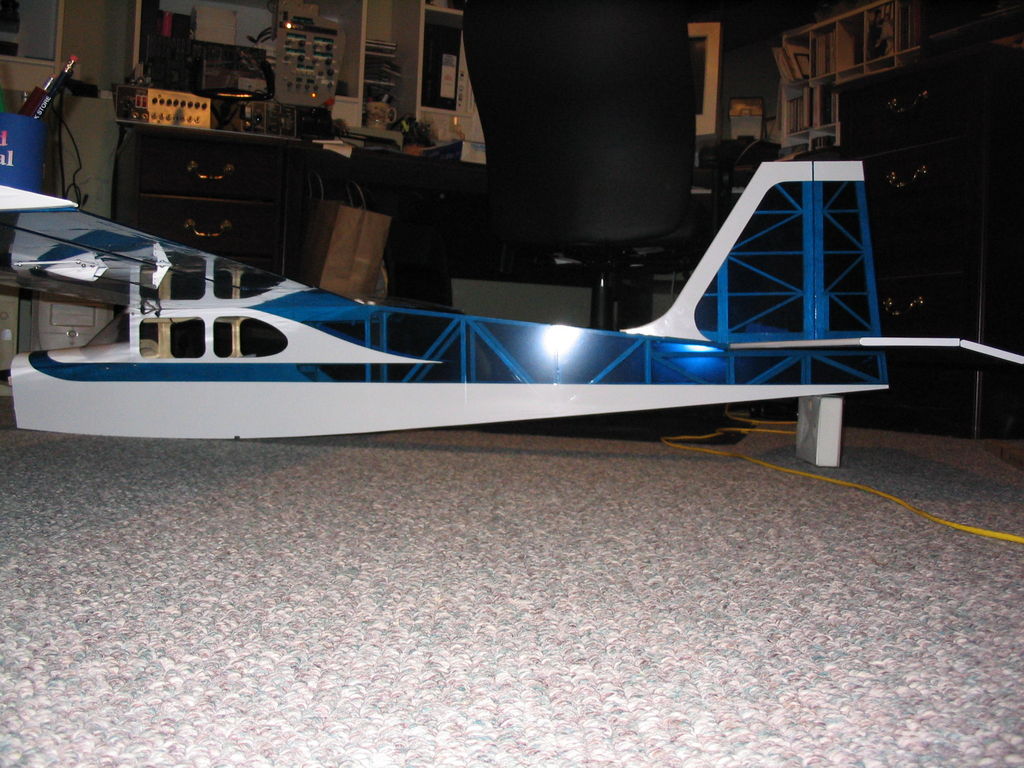
May 8, 2005.
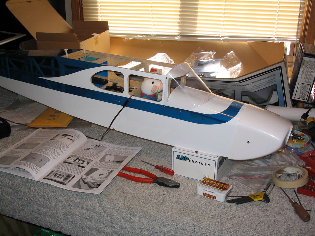
Today I installed a remote fuel valve, as well as a 12×6 prop and the spinner. I screwed on the cowl, and tighted up the muffler. I then bolted on the wing and set it outside for some pictures …
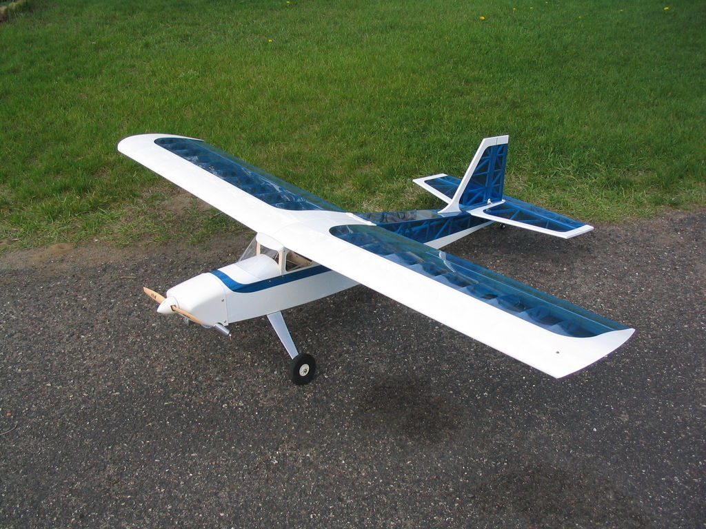
img_2502
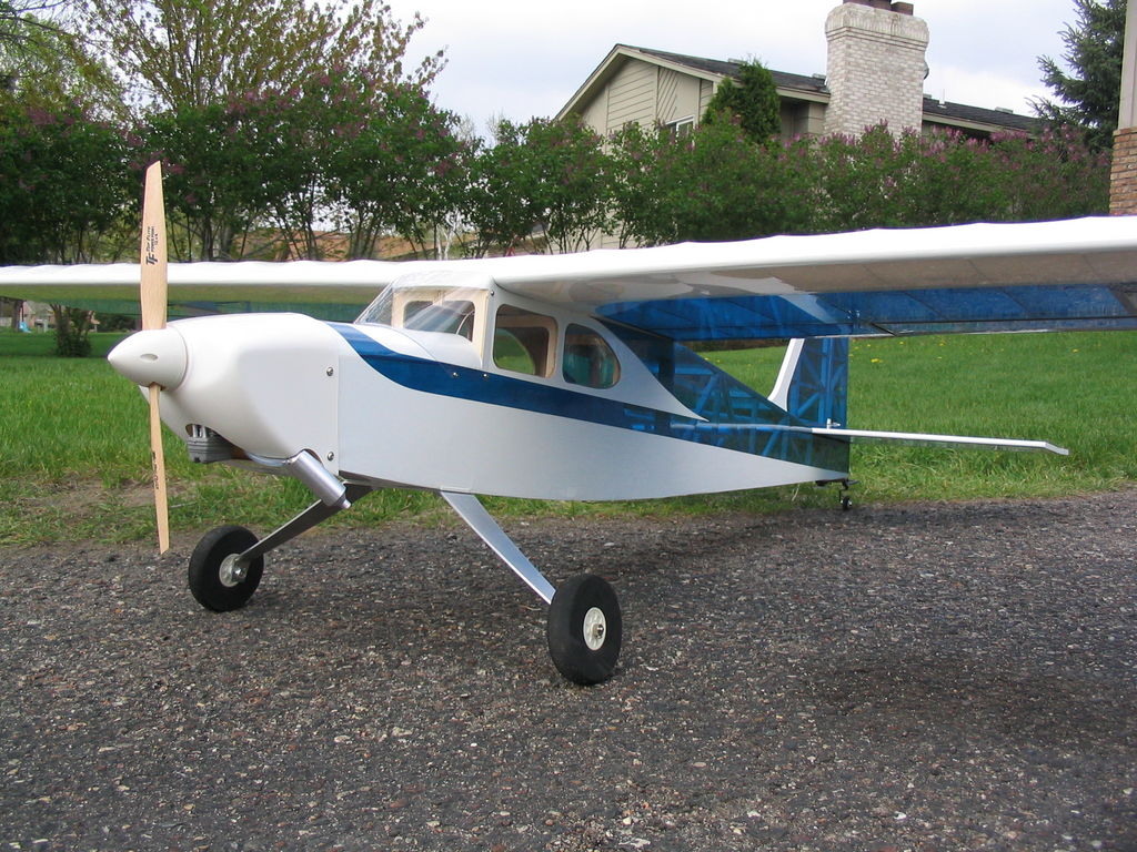
img_2504
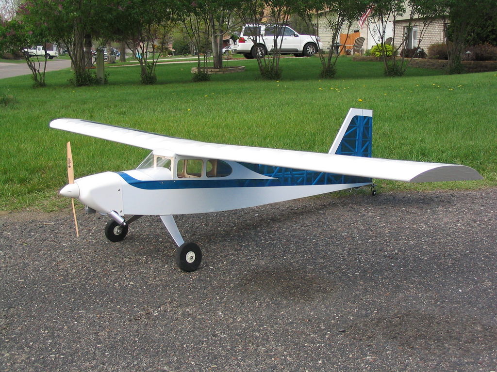
img_2505
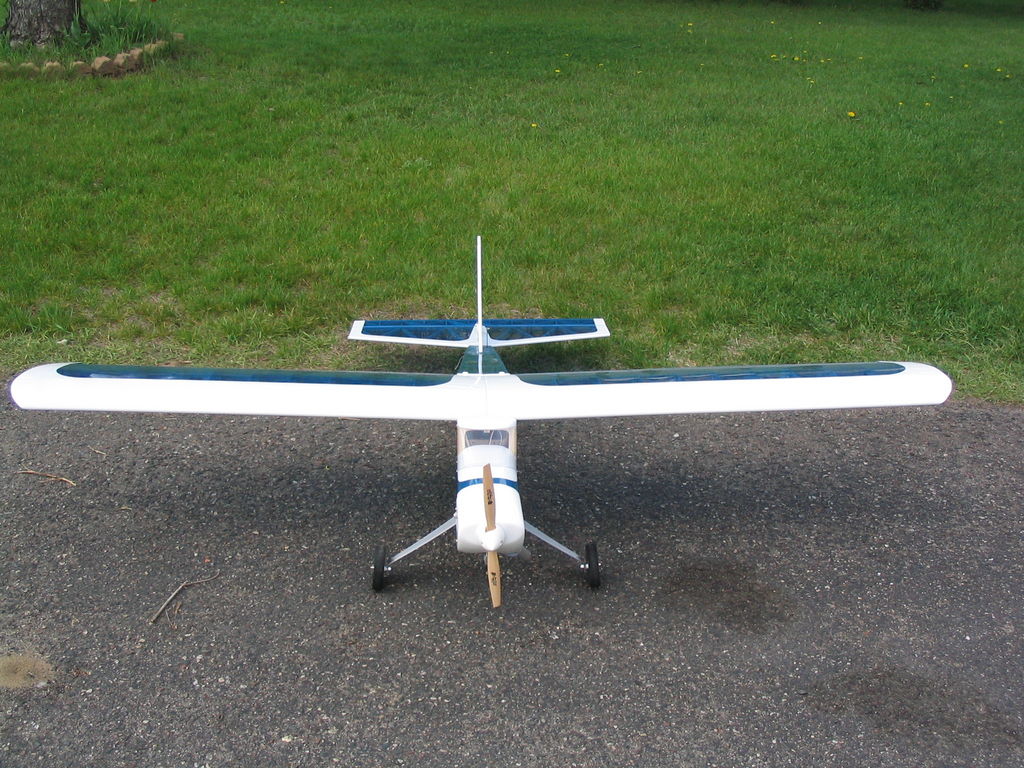
img_2506
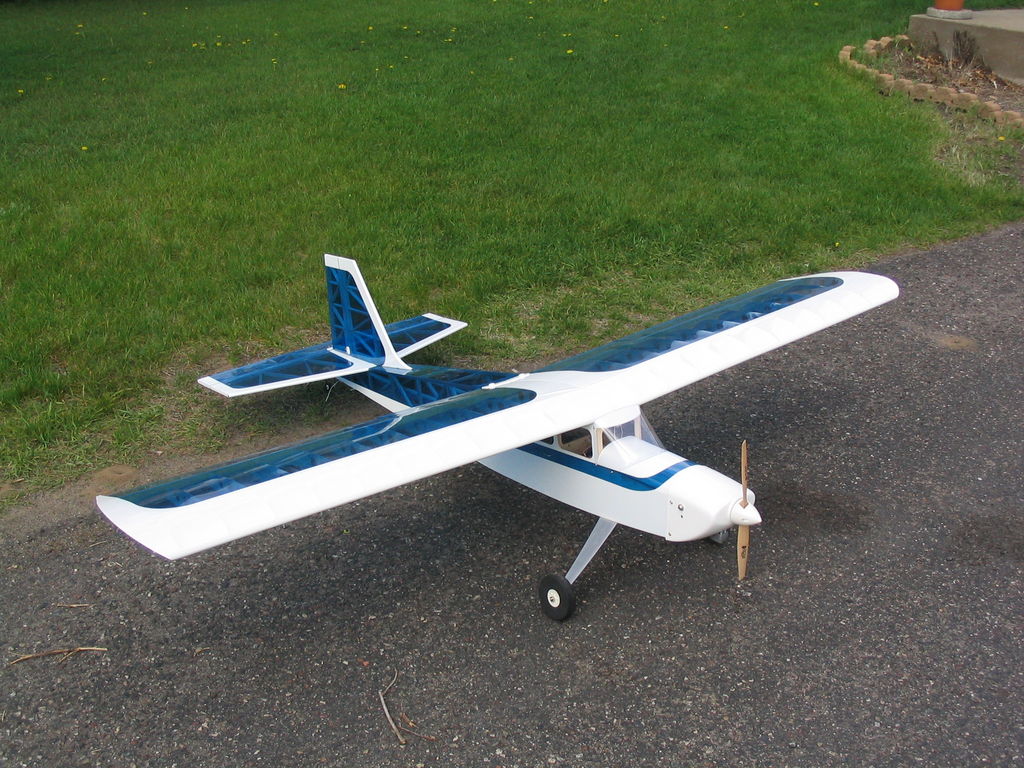
img_2507
May 7, 2005.
Today I finished off the main gear installation. The aluminum main gear was special ordered from TNT landing gear. I wonder if I should have ordered two so I could install floats someday? 🙂
img_2474
img_2475
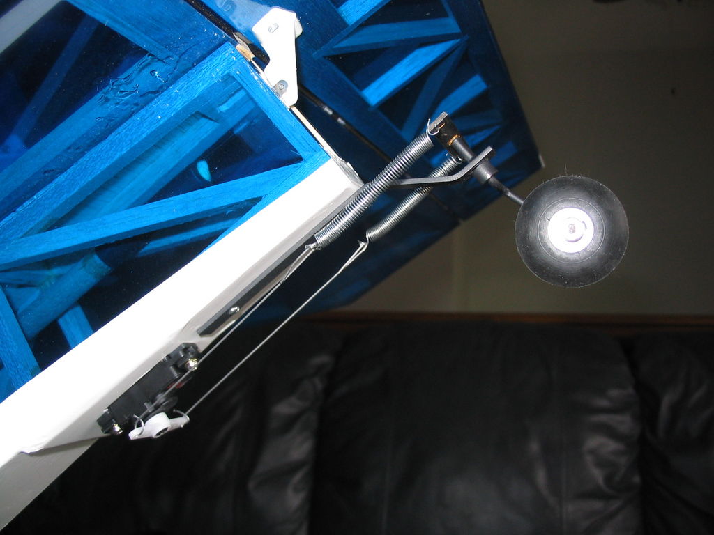
img_2478 I also padded the receiver and battery, and routed the antenna out the bottom of the airplane and to the rear. Finally I cut out and installed the side windows. It looks like she may come out a tad tail heavy, but I haven’t put the prop and spinner on yet. We are getting close to being ready for the maiden flight. It’s down to a few details now.
May 2, 2005.
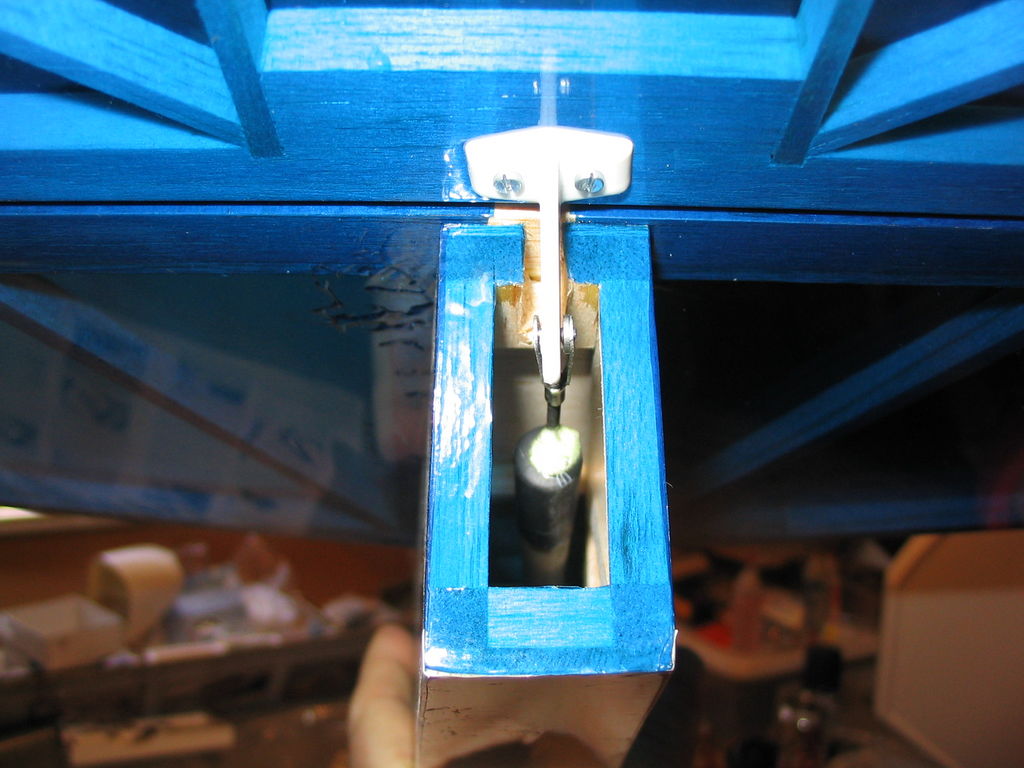
I had previously mounted the tail wheel and tail wheel servo, but I needed to rig up the pull/pull spring/wire system. Today I bought some thin piano wire and did just that. It’s not perfect, but looks fine from 10′ away and is solid structurally so I guess it will do.
April 23, 2005.
Maisy expressed interest in being chief test pilot …
img_2439
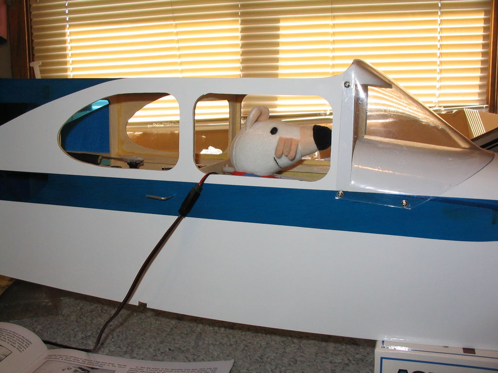
img_2438
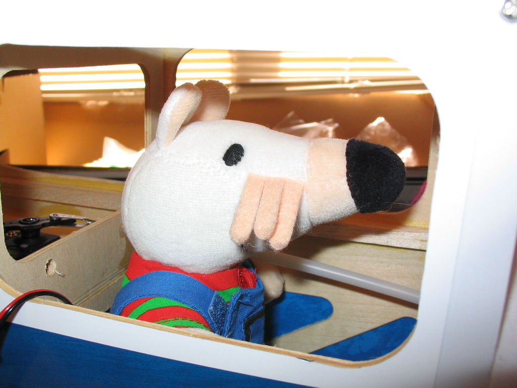
img_2437
April 23, 2005.
Last week I glued on the tail surfaces. Yesterday and today I installed the cabin servos. I then constructed the elevator and rudder pushrods, and installed them. The provided hardware/wire for one end of the pushrods broke when trying to make an “L” bend. Fortunately I had some replacement wire pushrods laying around that worked out just fine, probably better.
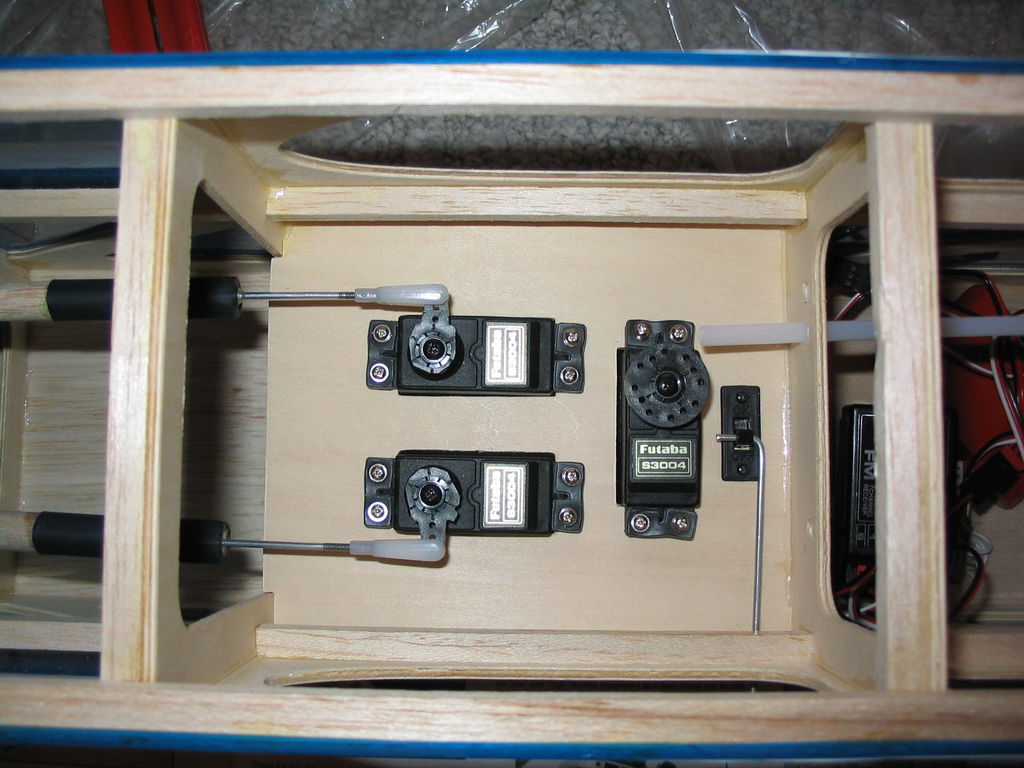
img_2432
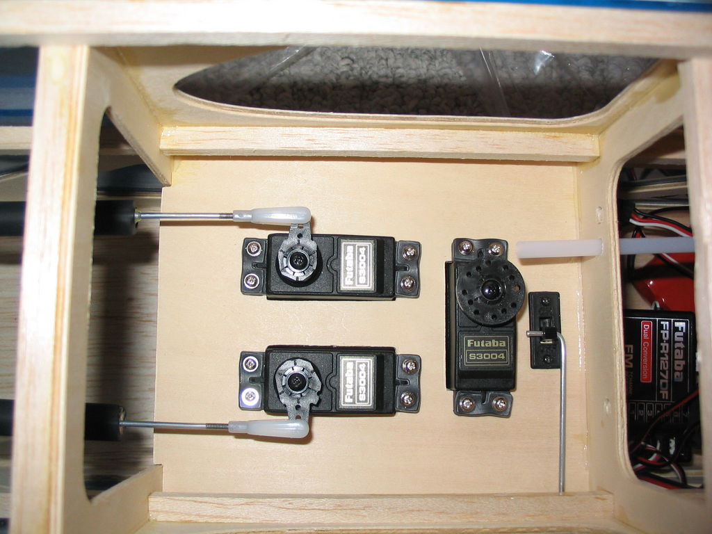
img_2433
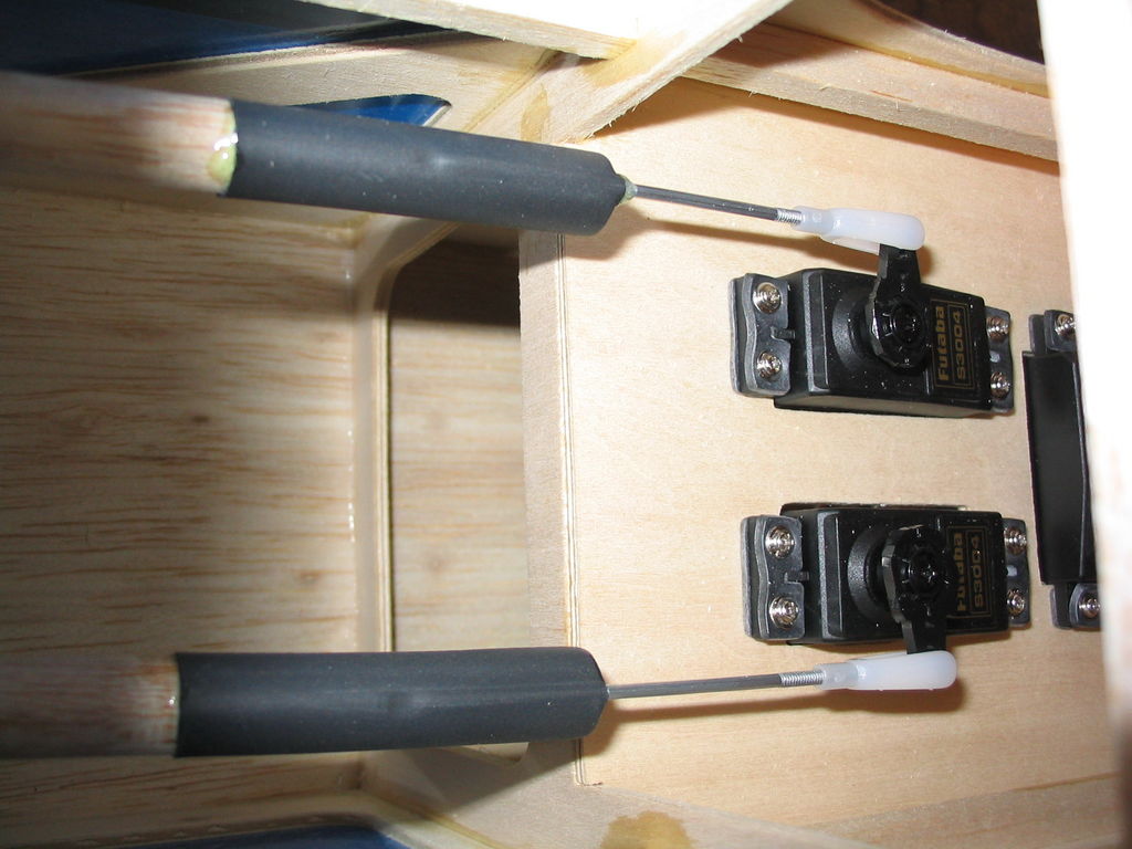
img_2434
img_2435
img_2436 I also fabricated and installed the throttle pushrod and connected it to the engine.
April 10, 2005.
Today I glued in the elevator and rudder hinges and then test fit the tail surfaces.
img_2426
img_2427
img_2428
img_2429 The tail surfaces are glued on with epoxy and care must be taken that the horizontal stabilizer is aligned with the wing (when viewed from behind), and also that it is perpendicular to the fuselage (when viewed from above). It should only require a small amount of balancing and leveling to achieve this, but 5-min epoxy means I have to work quickly. I also purchased a micro servo and tail wheel assembly for my tail-dragger conversion. I plan to plug a “Y” harness into the rudder port of my receiver and run two servos. A standard servo will control the rudder surface, and a second micro servo mounted in the tail will control the tail wheel steering. The servo will be linked to the tail wheel with springs so it won’t need to generate (or endure) a lot of torque.
March 6, 2005.
Today I drilled a new throttle pushrod hole. I filled all the extraneous left over fire wall holes (I moved the engine mount up, The throttle push rod had to move, and I am not using a nose wheel.) I also left two holes/routes (temporarily sealed) back to the main cabin if I ever want to install a larger tank. Finally, I sanded the cowl cutout so it is nice and smooth.
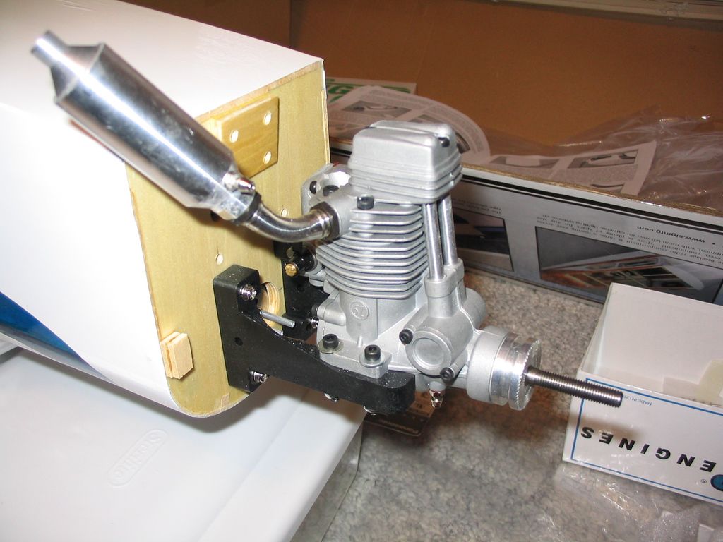
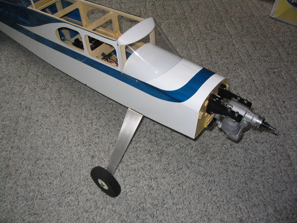
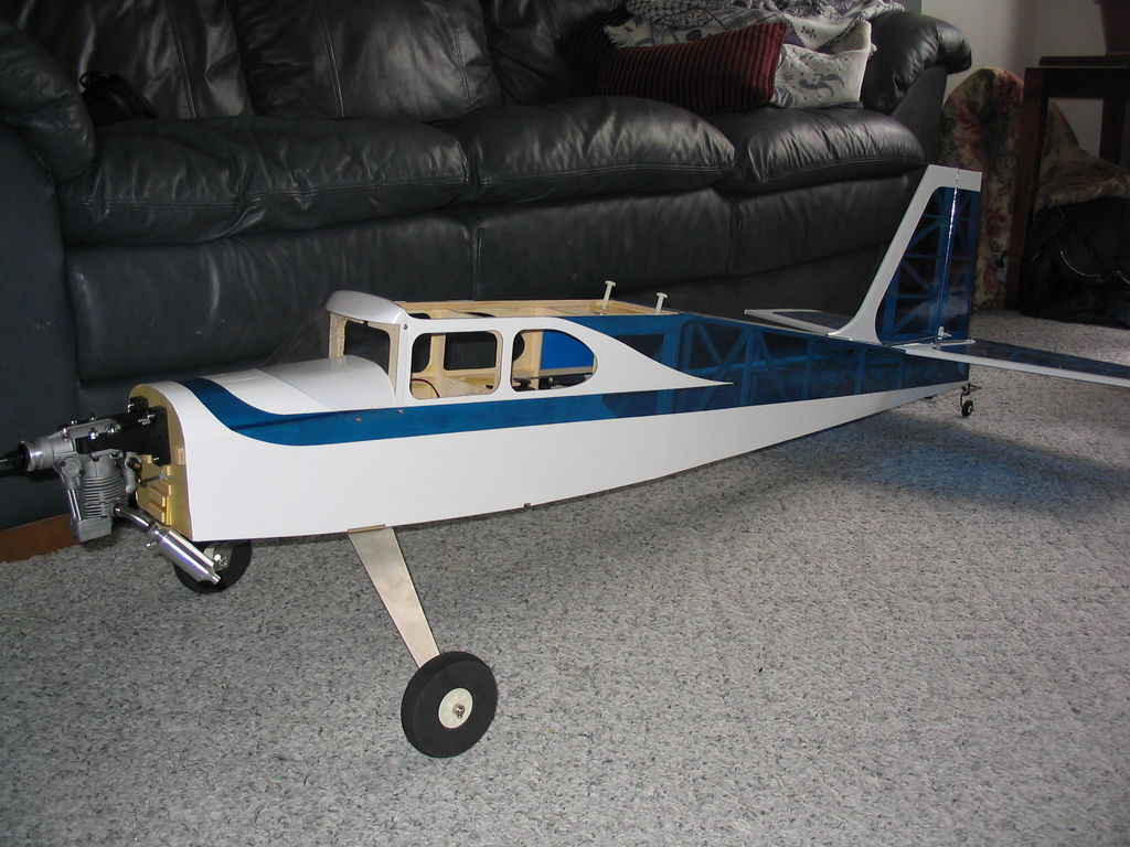
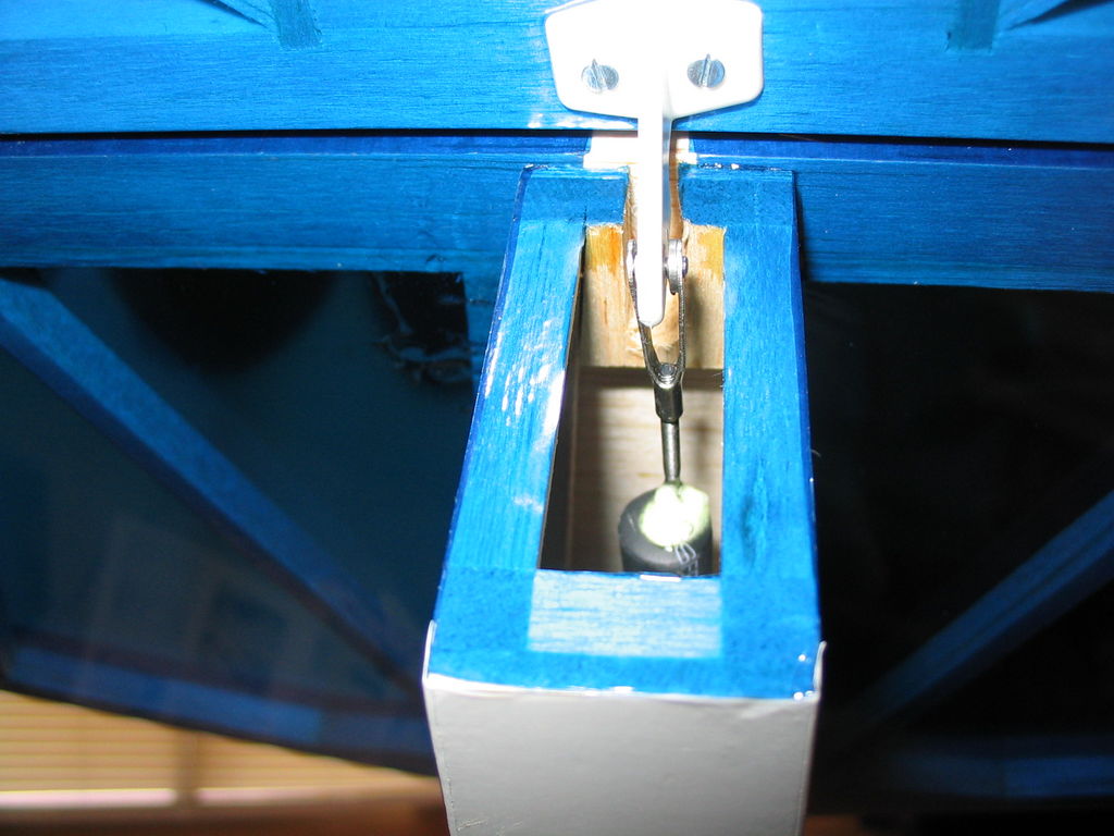
February 27, 2005.
For this project I have chosen a 4-stroke engine. This has caused me a fair amount of grief. With the default upright mounting scheme, the throttle arm is dead center with the tank; not exactly ideal. My final solution is to mount the engine upside down to the bottom of the motor mount arms, and move the mount up by the height of the arms so the thrust centerline stays the same. This keeps the motor mounts from needing to extend above the top of the firewall. This also puts a lot more of the engine inside the cowl and lets me use the original nose wheel push rod for the throttle. I need to be a bit careful about tank height vs. carb height, but we’ll see. I might want to add a pressurized fuel system to avoid this problem and allow me to install more fuel capacity.
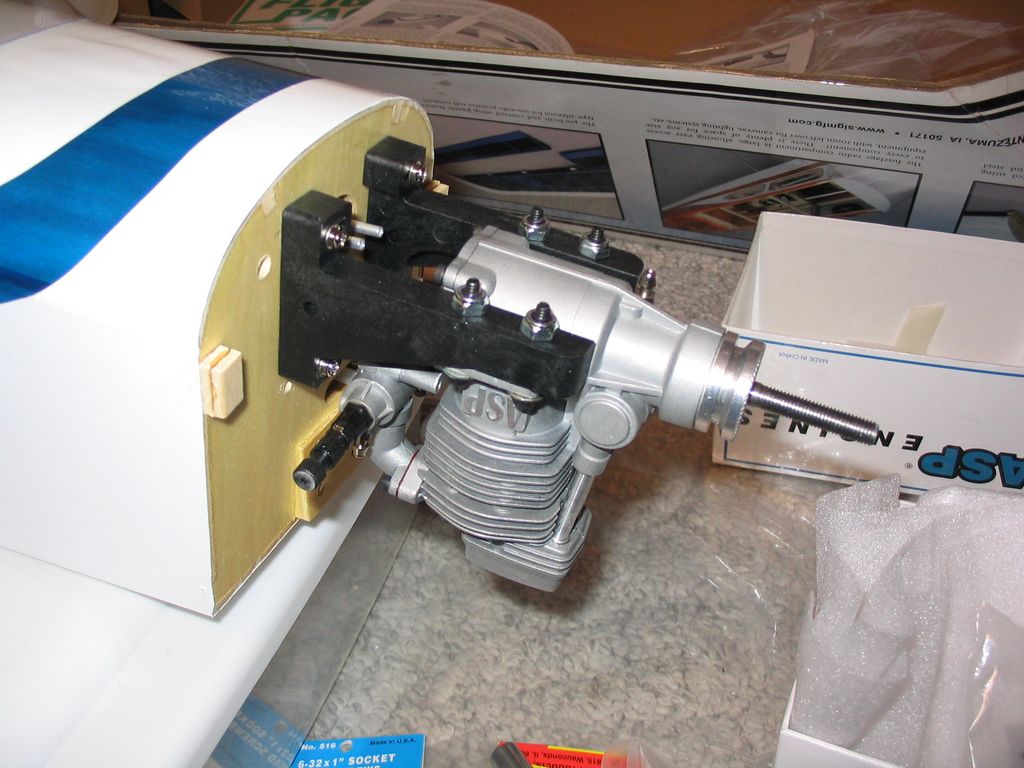
img_2375
img_2376
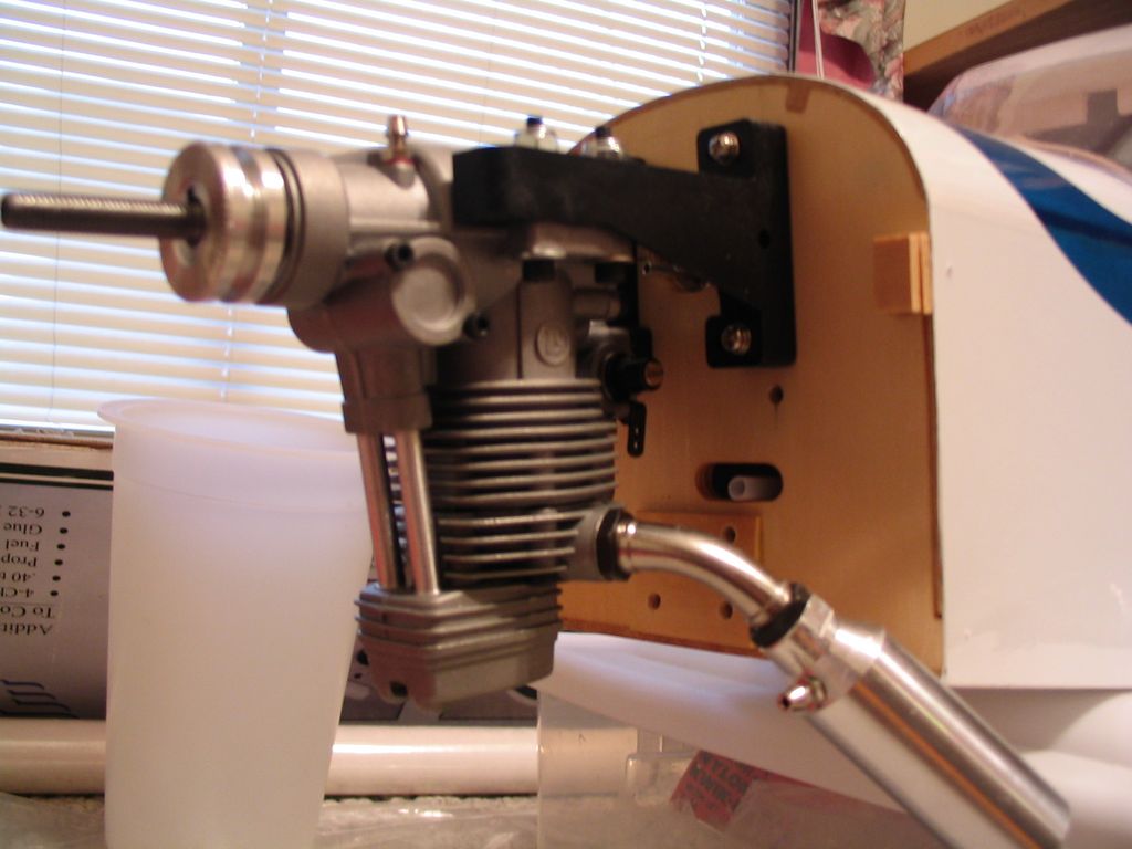
img_2380
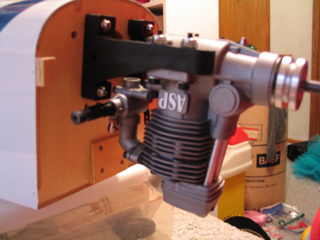
img_2383
September 18, 2004
I’m a little hung up on an engine mounting problem. This kit is setup to mount a 2-stroke engine upright, and everything is laid out perfectly for that. I’m trying to install a 4-stroke engine, and *everything* is in exactly the wrong spot for that … no matter what I come up with. Here’s a page I setup to describe my problem. Kadet Senior ARF 4-stroke mounting problem.
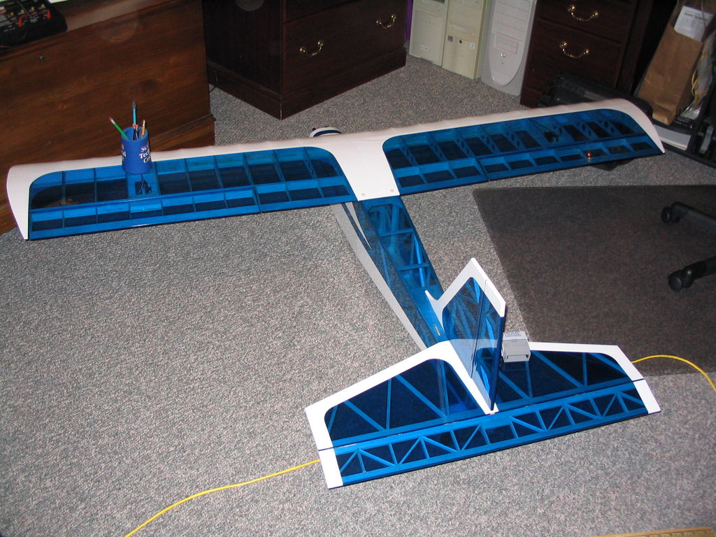
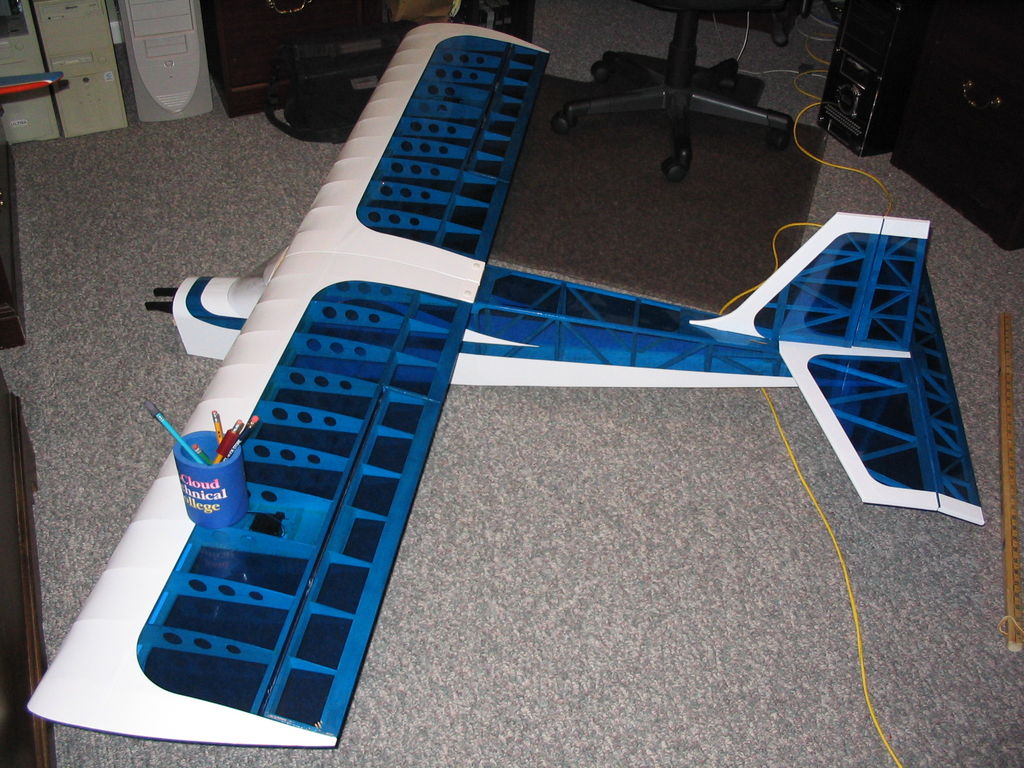
September 9, 2004.
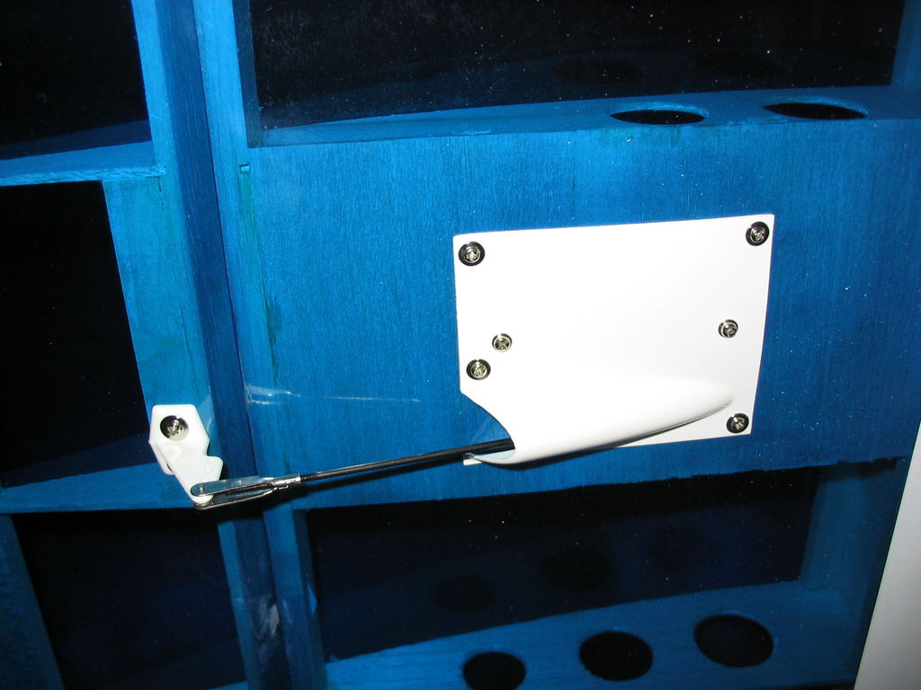
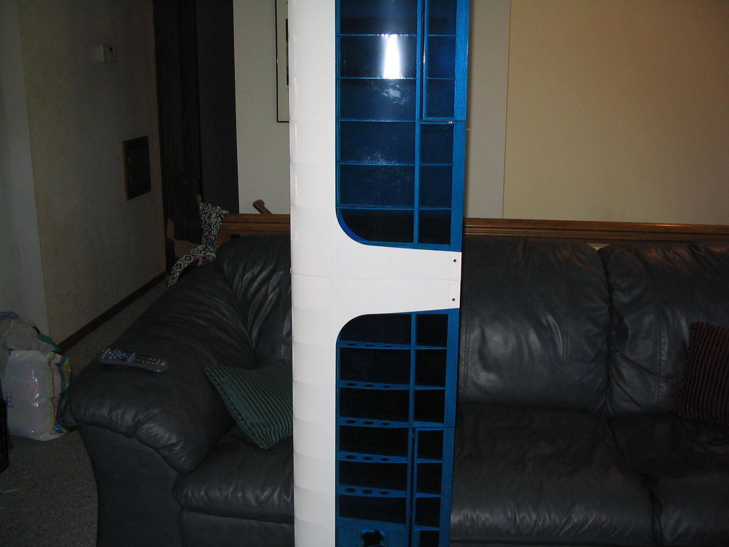
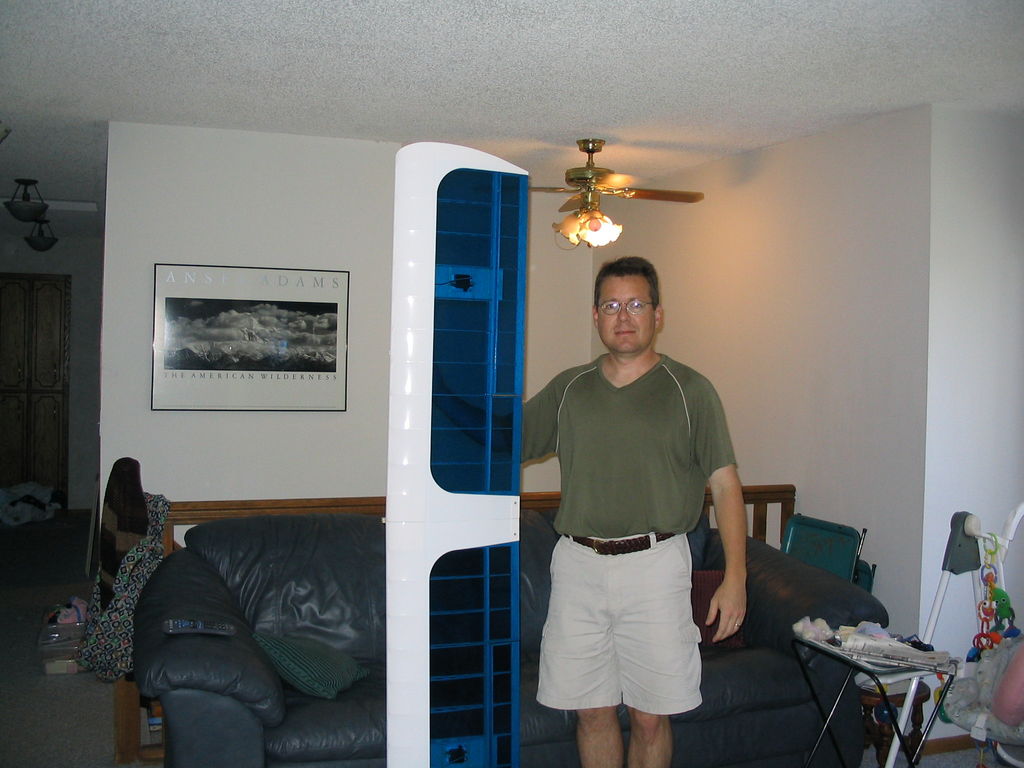
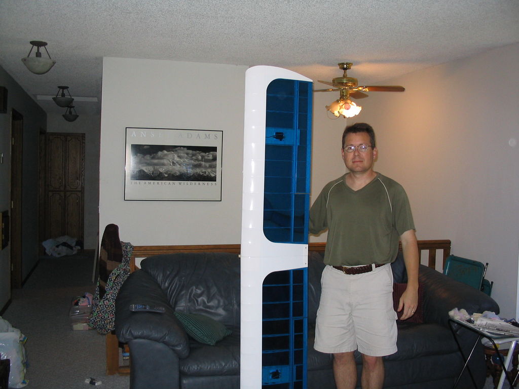
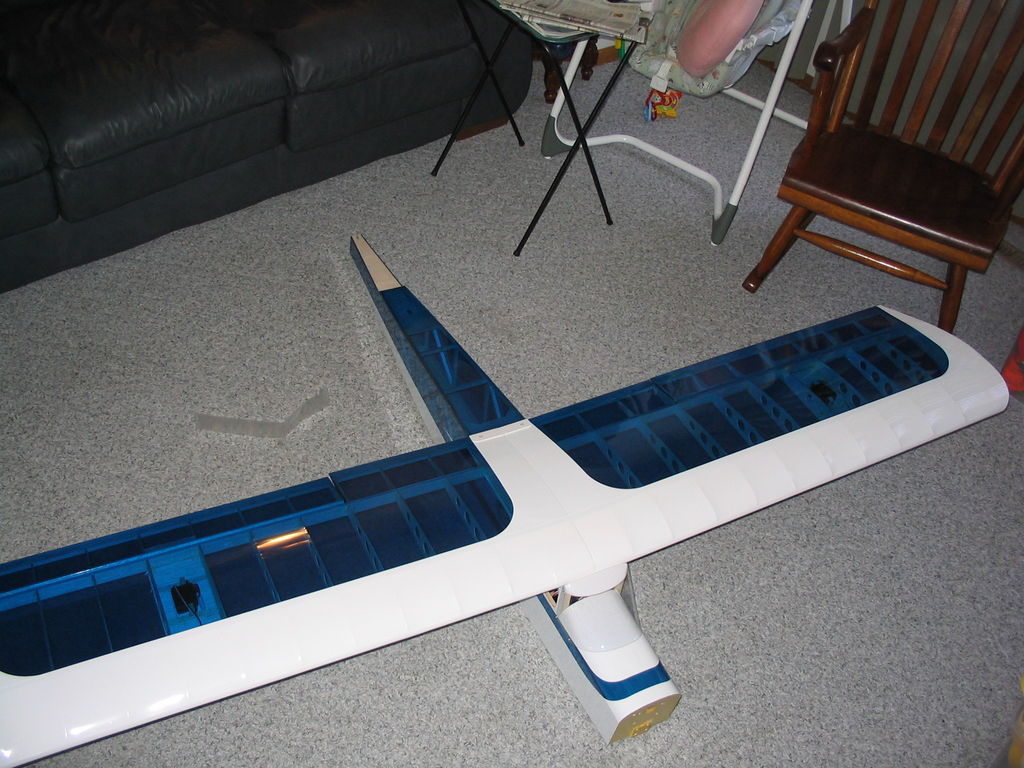
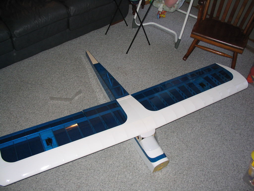
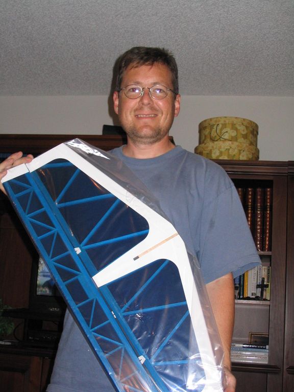
Today I took a few minutes from the daily grind and finished installing the aileron servos and linkages into the wings. For all practical purposes the wings are now finished and flyable. Here are some various pictures of the wing:
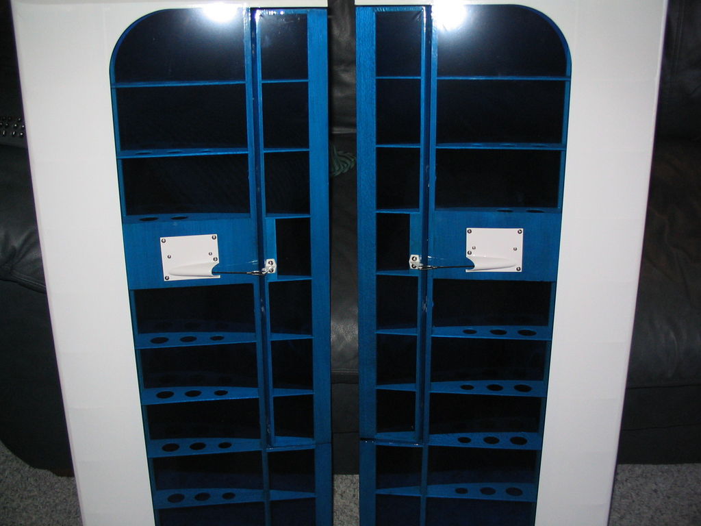
IMG_1950
IMG_1951
IMG_1952
IMG_1953
IMG_1954
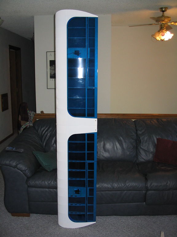
IMG_1955 Just to reference the size of this model, I’m about 5′ 9.5″ tall (1.77m for people outside the USA.) The wingspan is about 6′ 8″ (2.03m).
IMG_1956
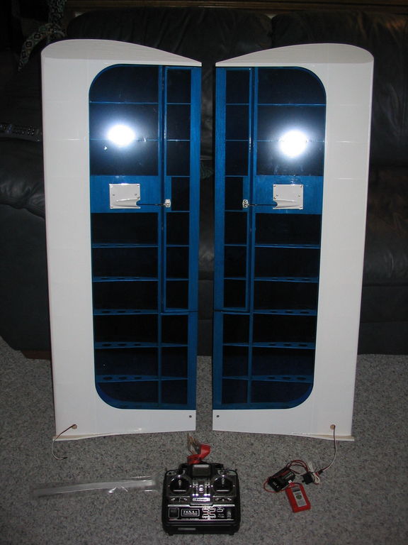
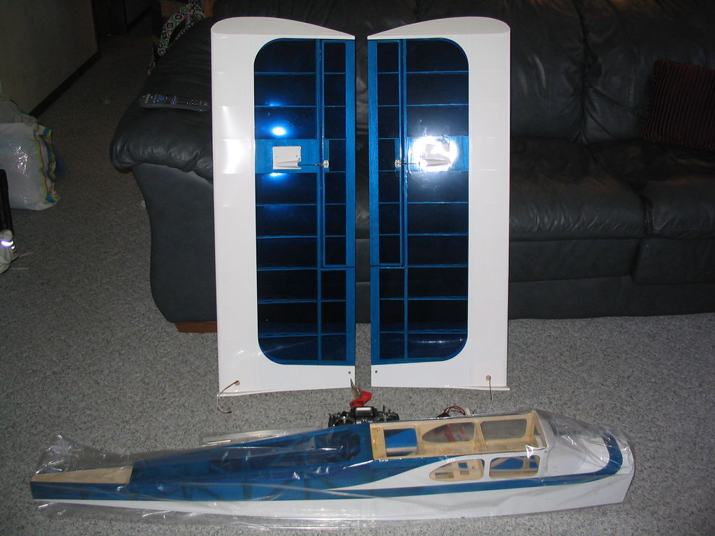
IMG_1957 And finally, here I am testing the fit of the wing with the fuselage:
IMG_1958
IMG_1959
July 14, 2004.
My engine arrived today. I purchased it off of ebay … a Magnum 61 four stroke, but was sent an ASP 61 four stroke. As best as I can tell they are the exact same engine from the same manufacturer, but the instructions are in Chinese. You get what you pay for I guess. Here are online Magnum 61 instructions. Just Engines sells ASP engines and parts.
July 12, 2004.
Today the flight pack arrived. I purchased it new from Tower Hobbies to match my existing transmitter brand and frequency. I also purchased an extra servo (one servo per aileron) and the necessary 24″ extension cables and a “Y” harness. I needed the aileron servos and extension cables to start construction so now I’m ready to begin.
July 1, 2004.
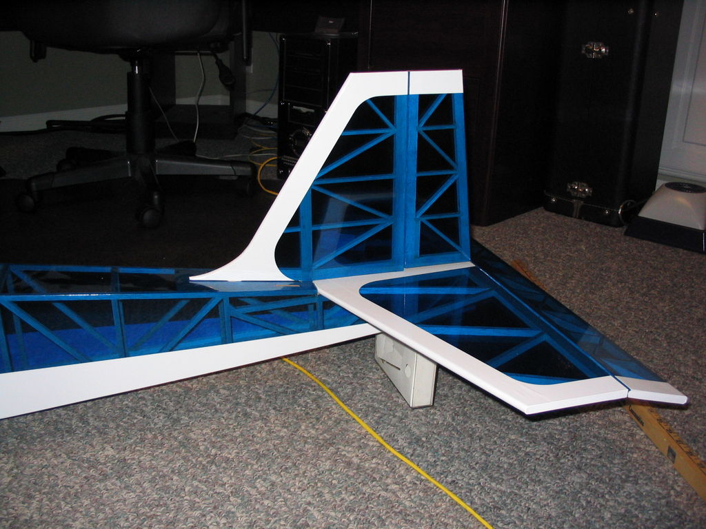
I purchased the airframe from rcuniverse.com “new in box” for about $50 less then I could get it from any hobby shop. It arrived today. Yikes! It’s huge! Much bigger than I expected!
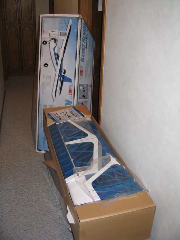
IMG_1603
IMG_1606