3D Modelling … with … Perl?!?
3D modeling with perl?!? What the…? Huh?!?
Are you insane? Yes, but in a nice sort of way (I hope!) 🙂
Since I’ve already admitted to being insane, you won’t mind if I explain the back story that let up to my evil plot. I work with a small high tech company (ATI out of Wasilla Alaska … and yes if you were wondering, but no I haven’t met her myself.) Some of the things we do is develop a variety of UAS related technologies. One project involves developing a marinized (water proof) UAS that can be launched from a small vessel and recovered in the water and generally operated with minimal infrastructure.
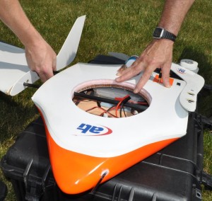
One of the guys on the project has wonderful artist talent and he hand carved the center section of our blended body flying wing design. It really looks sweet once it’s all together and in the air, but here is a close up of just the center section.
Well one thing leads to another and we decided we wanted to draw this up on the computer so we could cut molds, visualize and test design changes, etc.
But how the heck do you draw something like this. The only straight edges on it is where the wings plug in. The rest of it is totally free form and all blendy and curvy. I don’t see any cubes or spheres or cones jumping out at me. You are probably thinking of a few obvious approaches … make a mold from the prototype, laser scan it, etc. and sure those work for what they do, but they have draw backs … and we want the entire design on the computer and in a way we can play with it virtually.
As I started staring at the design and trying to analyze it’s structure and look at the outlines it occurred to me that the 3-view edges could be modeled pretty nicely with spline curves. I thought that if I could represent the outlines correctly, then I could create slices and march down the length (or width) sizing and blending my slices based on the 3-view outlines. At the end if I could only find a way to stitch the slices together, I would have a 3d model. That was the insane plan!
Spline Curves
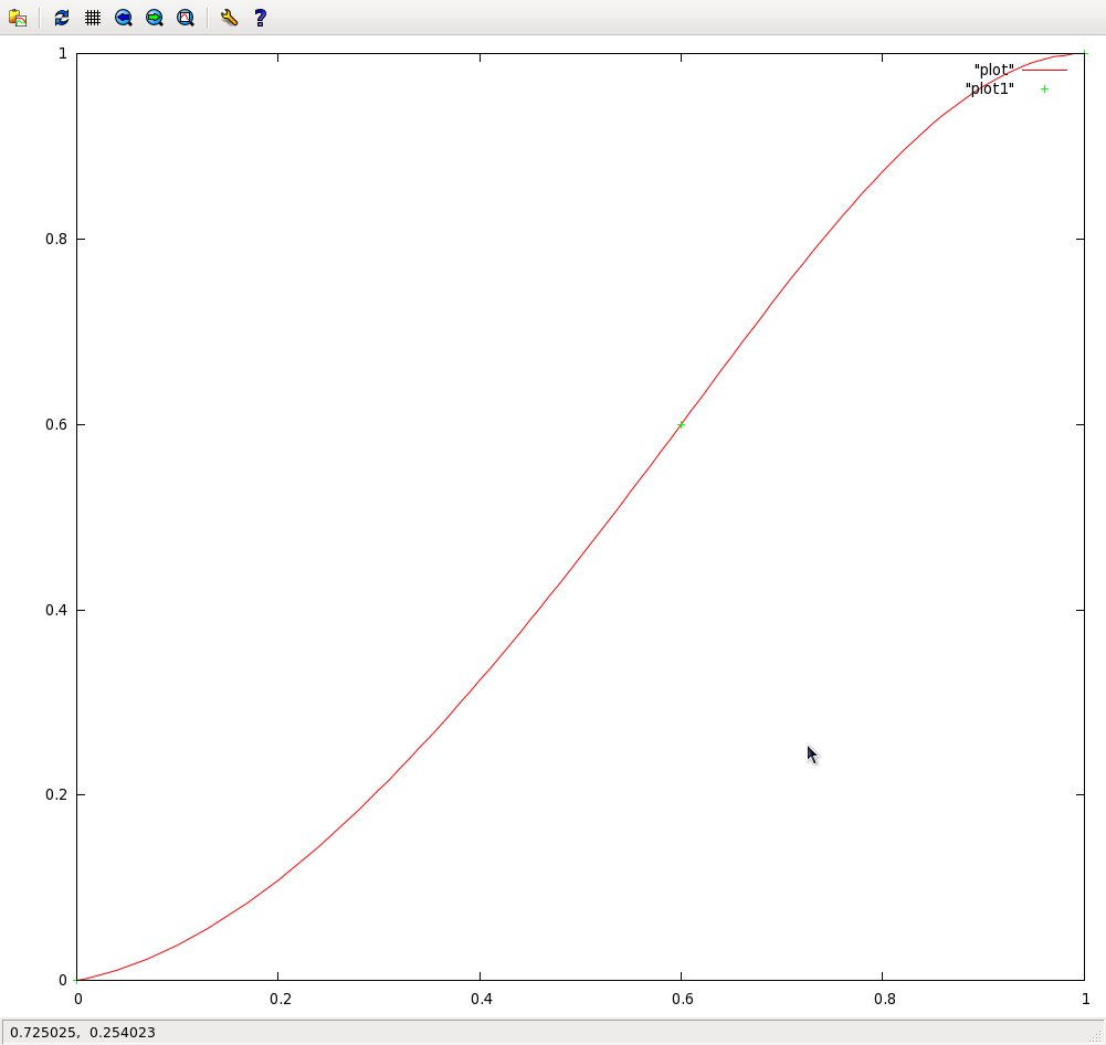
Here is a very simple spline curve. I could have used as many intermediate points as I wanted, but here I just have a start point, an end point, and one intermediate point. The curve will pass through all three points. In addition I can “clamp” the slope at each end. The following is a plot of a sample spline curve. With just a simple system like this I was able to model all the curves on our fuselage!
Top View
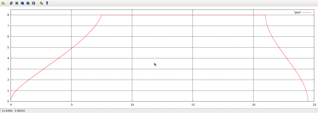
The following plot shows the right half of the fuselage from a top view (the front is to the left in this plot.) The leading edge is modeled with one curve, the straight edge at the top is where the wing plugs in, and the trailing edge is modeled with it’s own curve. Simple, and it’s already starting to look like something!
I don’t have a picture, but I did something very similar for the front view … one lazy curve from the top of the wing to the center, and a more aggressive curve from the bottom of the wing sloping quickly down and then flattening out along the bottom to maximize the volume inside.
Creating Slices
Next I’ll walk you through the process of creating slices. One thing I haven’t mentioned yet is I have the outline of the wing’s airfoil as a set of coordinates normalized from 0.0 to 1.0. This way I can easily scale the airfoil to any size I want. The way the model is setup, the slice that butts up against the wing has to be an exact match to the airfoil, but as I step towards the center, I need the slices to more and more take on the side view shape.
So lets start simple. At each slice point I lookup up the leading and trailing edge positions from the top view curves. I use these points to simply size and scale the airfoil. I’m not worried about height or blending into the fuselage shape yet. When I plot out my different size airfoils they look like this … cool. But notice that the the leading edge of each airfoil size is horizontally the same as each other which doesn’t represent our model and makes the center of the shape much taller than at the wings.
The next step is to raise or lower each slice (and size it vertically) so that in addition to following the correct leading and trailing edge profiles, the slices also follow the correct top and bottom profiles. Here is what it looks like: Ignore the lines in the center, those are just an artifact of dumping all the slices into a single line plot. This is improving but there are still some things to notice. Obviously there is a problem at the trailing edge and also the thickest part of the airfoil is moving forward. We want the thickest part of the airfoil to stay in the same place as we move inboard with our slices.
In this next plot we divide the airfoil shape at it’s thickest point so we have a front and a back. As we march inwards (longer airfoils) we keep the center point fixed and streeeech out the front portion. (again ignore the horizontal line garbage.) The front of our model is starting to look really good! The trailing edge needs work.
In the next plot I simply align the trailing edge height of every slice to match the trailing edge of the wing. This cleans up the model even more and it’s really starting to look like something. However, we are still using the airfoil shape in the back half and we need to blend that into the center line shape so we have more volume in our center section.
The next plot shows the correct center section outline in the bottom rear (the top rear still needs work.) It’s hard to see from this plot but the bottom rear portion of the slices close to the wing match the wing airfoil shape and as we march inwards, they slowly blend into the correct fuselage shape. We need to do the same thing with the top rear of the slices.
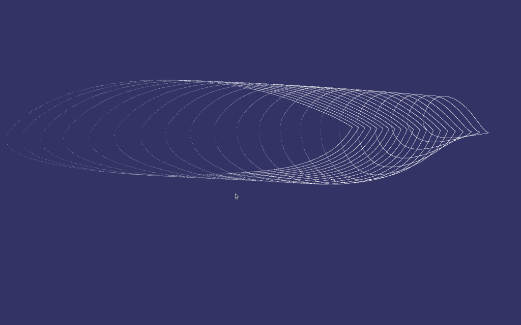
The following plot is almost identical to the previous one except the top rear (left) has been curved outwards to make more internal volume. Again we match the airfoil shape near the wing and blend to the fuselage shape as we move inboard. This is the final plot. All our slices are looking really good!
Going 3D!
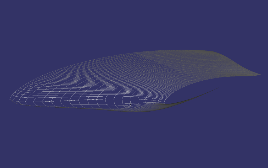
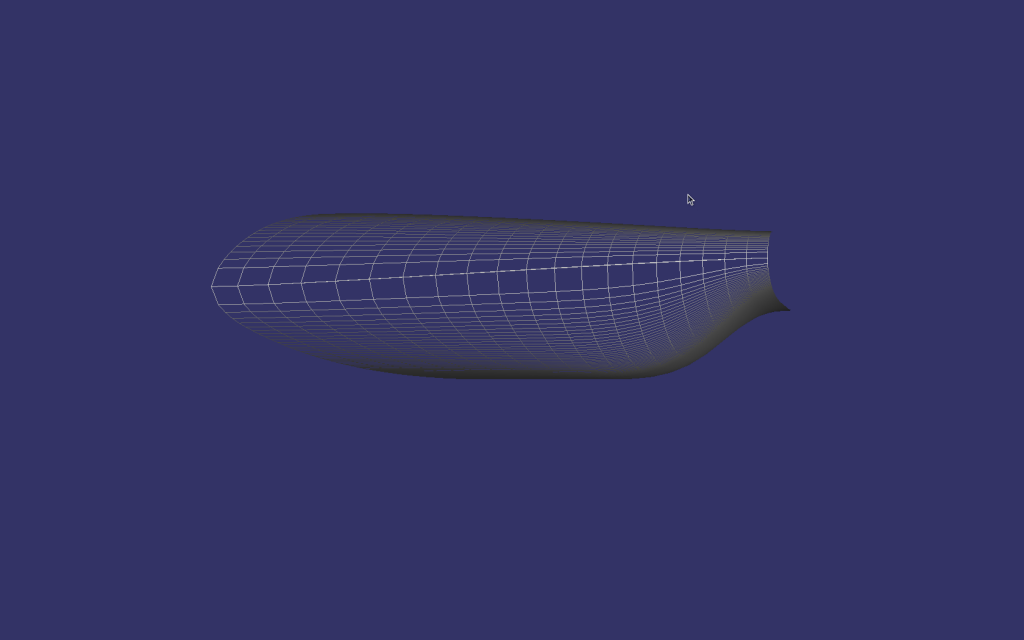
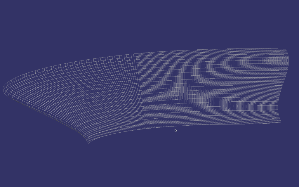
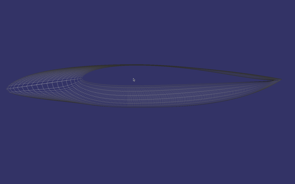
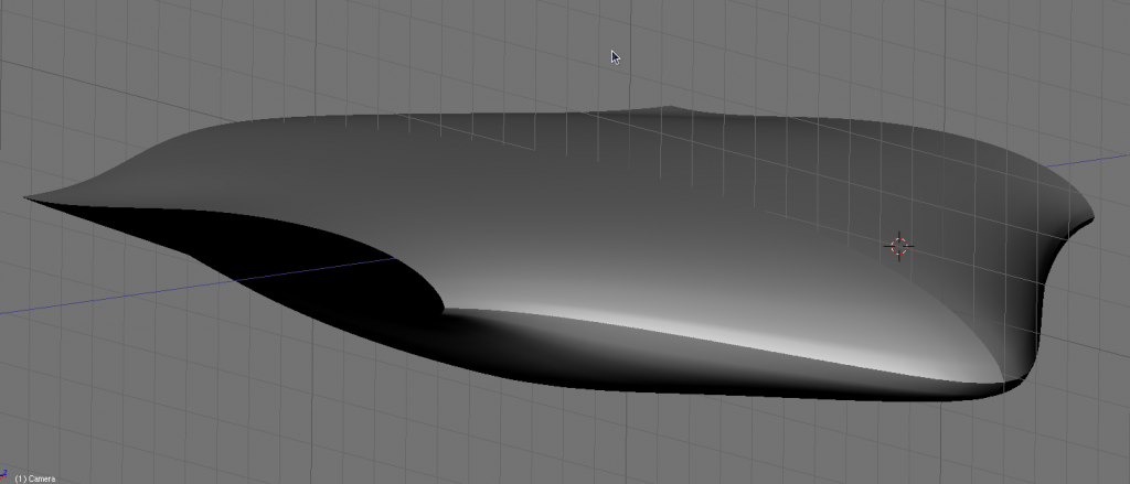
The next task is to figure out how to stitch all the slices together to make a 3d surface mesh. Here are a couple technical details. I output the AC3D format because it’s a well supported (in the open-source world at least) and has an easy and well documented ascii format and structure. I won’t say too much about it. Basically I walk through each slice and create triangles that connect the points up with the neighbor slice. You can see the resulting structure from the following 3d pictures.
Because the model and the slices are all script generated, I can easily set how many slices to create and for each slice how many “chops” front to back I create. With a tap of the keyboard I can generate an incredibly finely detailed model to send to a CNC machine, or a more coarse model for real time visualization or simulation.
All the curves and dimensions are paramaterirzed, so if I want to change the length of the nose or the tail, adjust the overall depth, fiddle with the shape of the curves … it is all very easy and quick to do.
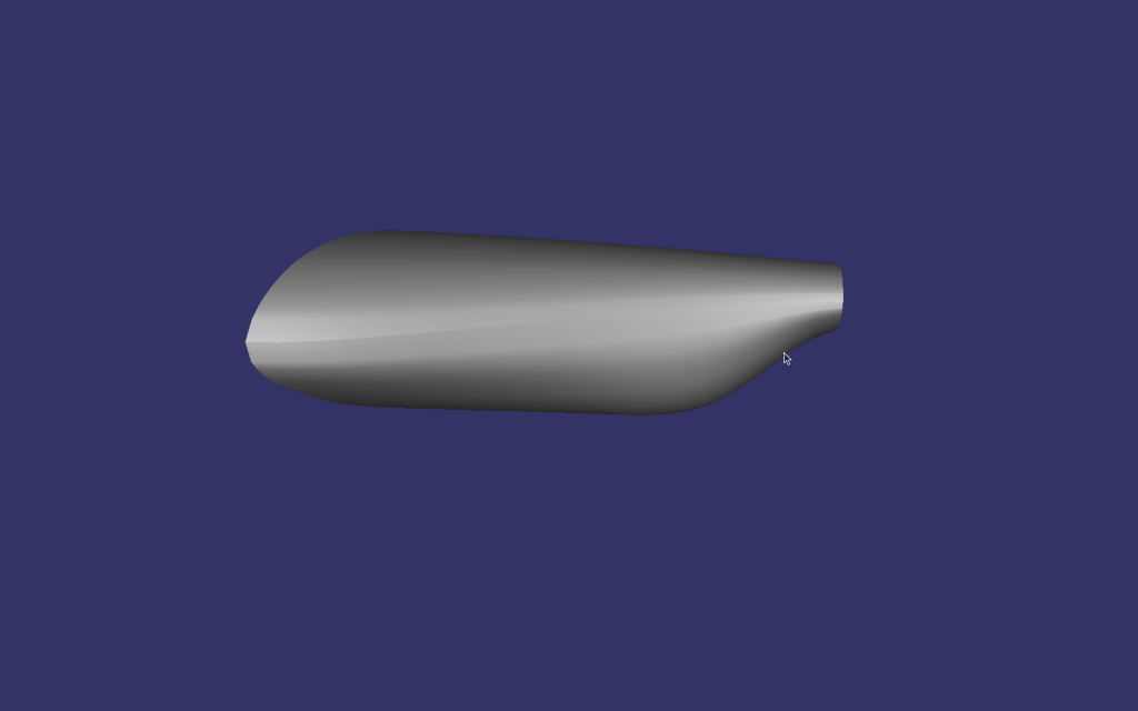
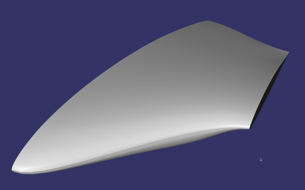
Here is the final 3d shape that is beautiful, sexy, and blendy and very closely matches the artist’s original hand carved prototype. (I just show the left half, because you know, mirroring the other side is just a bunch of busy work.)
Feel free to click on any of the plots or pictures in this post to get the full size version.
So there you go, a slick little 3d model generated by a perl script that lovingly captures the artists original concept and in a few areas goes a step further with curving and blending the shapes together.
