Real-time UAS Simulation and Visualization
Real-time UAS Simulation and Visualization
In previous posts I’ve described the process of carefully modelling the basic geometry and mass properties of a UAS in YASim to provide a real time flight dynamics simulation of the aircraft in FlightGear. I also described how we carefully modelled the blended body shape of our UAS using airfoil plots and spline curves. These curves were then imported into MoI and used as the basis to generate a smooth, flowing, organic surface shape. MoI is able to export the model as a 3d triangle mesh in a variety of formats including 3ds.
Model Cleanup
FlightGear can directly import 3ds models and render them in the simulator. However, I found that my model needed be cleaned up in several respects. All of this discussion relates to Blender – a very capable open-source 3d modeling tool. This isn’t intended to be a blender tutorial, but a brief overview of the steps involved in preparing a model for use within FlightGear
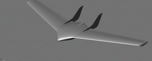
- Surface smoothing: If you click on the above thumbnail you will see that the basic model imported from MoI is “faceted” or in other words, the triangle surfaces are flat and you don’t see the intended smooth curved surface. One of the first steps required is to select each “Object” and select “Set Smooth” in the “Buttons Window”. Repeat for each object in the model.
- Inside-out surfaces: I decided for simplicity, I would export the model in the .ac3d format (a text based format) for final use in FlightGear. When I did the export I discovered many of the surfaces where inside out — the face normals were pointing in rather than out. This causes the surface to be displayed inside out and shaded wrong in FlightGear. So the next step required is to turn on the display of face normals, select each object individual (right mouse click), enter “Edit Mode”
key, and flip the face normals if needed. - Orientation: FlightGear allows you to add an xml wrapper around your model to adjust the orientation of your model (flip it by 90 degrees for example) in case the model was developed for a different coordinate frame layout. However, since I was doing all the prep work anyway, I rotated the heading of my model by 90 degrees in blender so I didn’t need any extra transforms when drawing the model inside FlightGear.
- Scaling: For convenience and due to the scale of this design, all the original work was done in inches. This transfered to the MoI model and thus to the blender and flightgear models as well. However, FlightGear requires units of meters so the model was grossly oversized when imported into the simulator. Blender has a scale function, so I selected the entire model and scaled it by a factor of 0.0254 to convert from inches to meters.
- Control Surfaces: this aircraft is a flying wing and has as very simple control system. Each wing has a strip elevon that runs the length of the wing. Aileron and elevator inputs are mixed (summed) to produce the actual control surface deflection. In the real UAV, this mixing is accomplished in the flight control software. On an RC airplane this mixing would be done inside the pilot’s transmitter on the ground. In FlightGear, the mixing is done through the YAsim xml config file. Blender has a cut function accessed by typing “Shift-K”. I went into top view mode, drew lines for the control surface cuts and cut the mesh to create the elevons.
Textures and Painting and UV Unwrapping
This could be the subject of a book just by itself, but let me give a really quick summary.
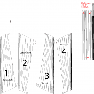
Blender has a cool feature called “UV Unwrap” which is found in the “Mesh” menu when you are in “Edit Mode”. There are several unwrap options, but I found “Unwrap (Smart mode)” worked the best for my purposes. The following image shows how blender unwraps the mesh (in this case the wings and elevons.) In the bottom panel I selected “UV/Image Editor” and it shows the unwrapped mesh image.
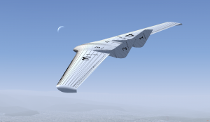
Now here’s the cool thing. You can save this image out to a file and then import it back in. Blender will use the imported image to texture the file exactly as it has been unwrapped. So with this template image you would see a model that looks like a wireframe. I then loaded up the images in blender and labeled each panel with a big number. Inside FlightGear (or osgviewer) I could then identify which number corresponded to which panel (top left, bottom right, etc.) I further edited the template file to include this extra information. The result when drawn in FlightGear looks like this:
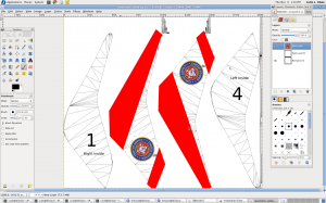
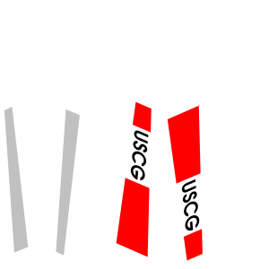
Now I have my “paint kit”. I can load up the templates in gimp (or photoshop), create a new layer, and draw my color schemes and markings over the top. For the wing panels, I did a quick hack of a coast guard-ish color scheme which looks like this:
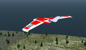
I then export just the marking/paint layer back out to my texture files that the model references and the “finished” result looks like this:
This is still a work in progress. I have yet to animate the control surfaces. I also need to add a spinning propeller. The paint scheme is just a quick example and could use many many improvements.
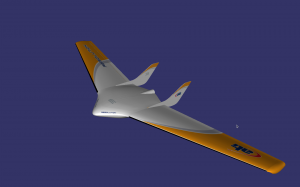
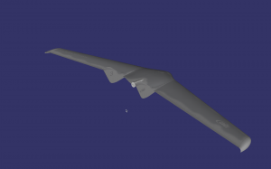
With the paint kit established, a variety of paint schemes can be developed. Here are two more examples:
Official ATI scheme:
A gray camouflage scheme:
Summary
There are many steps required to model a new aircraft design in FlightGear. Primarily this involves creating a flight dynamics (physics) model and a 3d model of the design. Each step requires several sub-steps and there is always room for improvements and refinements. This is an example of an R/C scale UAV. Full scale aircraft are much more complicated involve detailed cockpits, many more animations, much more complicated 3d meshes, and much more work texturing and painting. Hopefully I have provided a taste of what’s involved. With a little effort any one can jump in and learn the tools to build simulated aircraft. But it does take time and patience.
Finally, here is a (sorry, kind of crude) youtube video showing the model flying inside FlightGear:
