New Hardware Design Project
Feb 11, 2018 update: After some amount of tearing my hair out and some help from the beaglebone IRC community, I have the pocketbeagle UART2 configured and working to my external connector. Telemetry is up and running! I also plugged in an SBUS receiver, verified it is getting power correctly, bound it to my transmitter, and then verified the system is seeing my pilot inputs correctly. Next up: verifying all 8 pwm output channels.
Feb 10, 2018 update: Back to my v2.0 board build. I soldered on the gps connector and am now getting gps data into the teensy and relayed to the pocketbeagle. Now my autopilot code has gps + imu and compute it’s attitude @ 100hz.
I haven’t done much low level circuitry in my life, so the next thing was to solder on two resistors to complete my voltage divider circuit. This lets the board sense it’s own avionics voltage (output from the onboard regulator.) This is a “nice to know” item. It’s a good preflight check item, and a nice thing to make sure stays in the green during a flight. The result is 5.0 volts spot on, exactly what it should be, cool!
Version 2.2 of this board will also sense the external voltage in the same way. This would typically be your main battery voltage. It is another good thing to check in your preflight to make sure you have a fully charged and healthy battery before launch. During flight it is one piece of information that can help estimate remaining battery.
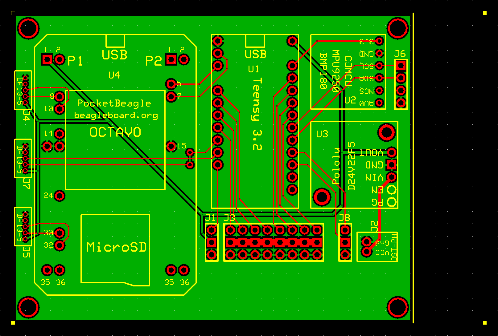
Feb 8, 2018 update: I have completed v2.2 of my board design using KiCad. I really like the kicad workflow and the results. I uploaded my kicad file to Oshpark and it can generate all the layers for production automatically. I don’t need to handle gerber or drill files unless I want to do it that way. Here is the Oshpark rendering of my board! From other oshpark boards I’ve seen, this is exactly what the real board will look like.
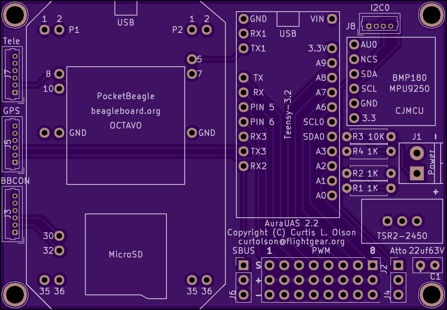
The aura hardware designs are ‘open-source’. All the kicad design files can be checked out here: https://github.com/AuraUAS/aura-hardware
My plan is to finish building up the v2.0 board I have on hand. (Keep moving downwards to see a picture and movie of the v2.0 board.) It is very similar but designed with ExpressPCB and ordered from them. I found a few small issues with the v2.0 board and that led in part to learning kicad and testing out this new path.
Feb 7, 2018 update: I put a momentary pause on board assembly because I discovered I was missing a couple bits. I placed an order to mouser and those items should arrive shortly. In the mean time I started experimenting with kicad (a fuller featured and open-source pcb design tool.) My long term trajectory has always been away from proprietary, locked-in tools like express pcb.
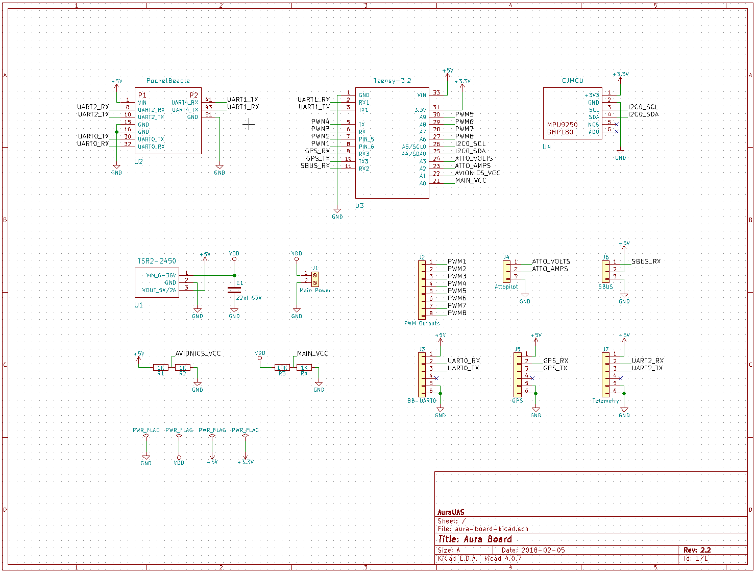
Here is my schematic redrawn in kicad. Using named wire connections, the schematic really cleans up and becomes easier to decode:
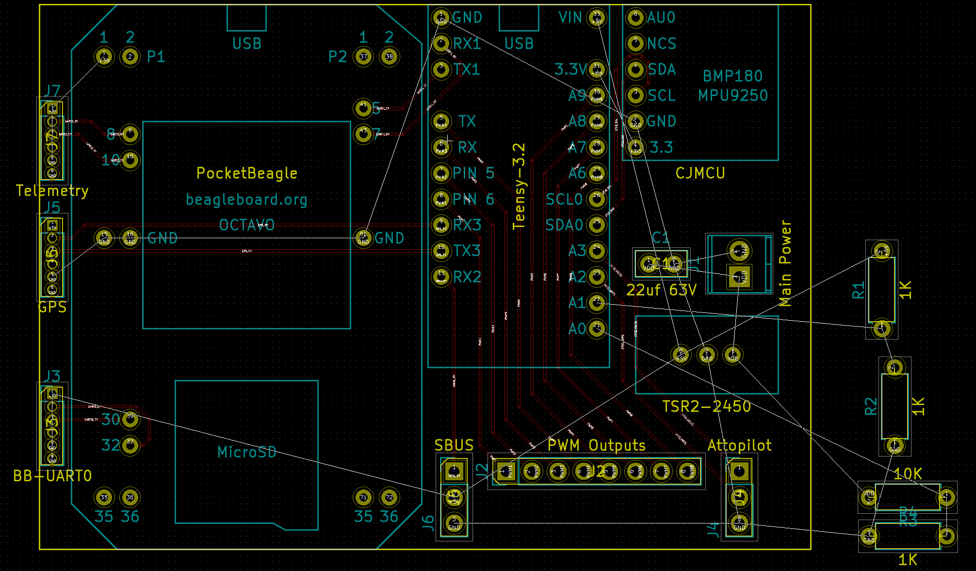
I have also begun the process of arranging the footprints and running the traces. I still have more to learn about the kicad tools and there is much work left to finish with the pcb layout editor, but here is what I have so far:
The benefits of using a tool like kicad is it outputs standard gerber files which can then be submitted to just about any board house in the world. This also means potentially much lower costs to do a board run. It also opens the door for me to experiment with some simple reflow techniques. In addition, there are pick and place shops I could potentially take advantage of in the future. The would potentially allow me to select smaller surface mount components.
Jan 31, 2018 update: It’s alive! I installed the 4 major subcomponents on the board this evening. Everything powers up, the software on the teensy and pocketbeagle runs, everything that is connected is talking to each other correctly. So far so good! Next up is all the external connectors and devices.
Jan 30, 2018 update: First board run is in! Here is a quick video that shows how it will go together:
Jan 14, 2018 update: I have replaced the board layout picture with a new version that reflects significant repositioning of the components which leads to simplification of the traces and better access to usb ports and microsd cards in the final design.
There is something relaxing about nudging traces and components around on a pcb layout. Last night I spent some more time working on a new board design which I present here:
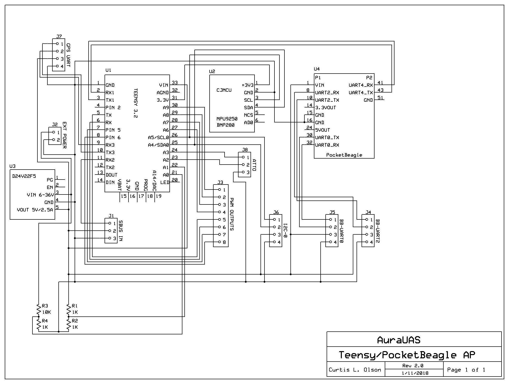
If you can’t guess from the schematic, this is a fixed wing autopilot built from common inexpensive components. The whole board will cost about $100 to assemble. I figure $20 for the teensy, $20 for the pocketbeagle (on sale?), $15 for a nice voltage regulator, $15 for the IMU breakout, $25 for the board itself. Add a few $$$ for connectors, cables, and other odds and ends and that puts the project right around $100.
The layout is starting to come together. It still requires some more tweaking. I’d like to label the connectors better, thicken the traces that carry main power, and I’m sure I’ll find some things to shift around and traces to reroute before I try to build up a board.
I am doing the design work in ExpressPCB, mainly because I know how to use this tool, and in the small quantities I would need, board prices are not a big factor. The board itself will cost about $25/ea when ordering 3 (that includes shipping.)
Version 2.0
This is actually an evolution of an autopilot design that has been kicking around now for more than 10 years. The basic components have been improved over the years, but the overall architecture has remained stable. The teensy firmware and beaglebone (linux) autopilot software are complete and flying – as much as any software is ever complete. This board design will advance the hardware aspects of the AuraUAS project and make it possible to build up new systems.
This new board will have a similar footprint to a full size beaglebone, but will have everything self contained in a single board. Previously the system included a full size beaglebone, a cape, plus an APM2 as a 3rd layer. All this now collapses into a single board and drops at least two external cables.
A few additional parts are needed to complete the system: a ublox 8 gps, a pair of radio modems, and an attopilot volt/amp sensor. The entire avionics package should cost between $200-250 depending on component and supplier choices.
Source code for the teensy firmware, source code for the beaglebone AP, and hardware design files are all available at the AuraUAS github page: https://github.com/AuraUAS