Hacking the APM2 Part #4: Laying out a 'hybrid' system
Imagine for one second that you are a UAV developer. The DIYdrones ArduPilot is an awesome piece of hardware; you love all the great sensors that are attached; you love the all-in-one design and the small/light size. But you are also feeling the limits of it’s ATMega 2560 processor and the limits of it’s 256Kb of RAM. And maybe, you enjoy developing code within a full blown Linux developers environment with all the supporting libraries and device drivers that Linux has to offer.
Hardware Layout
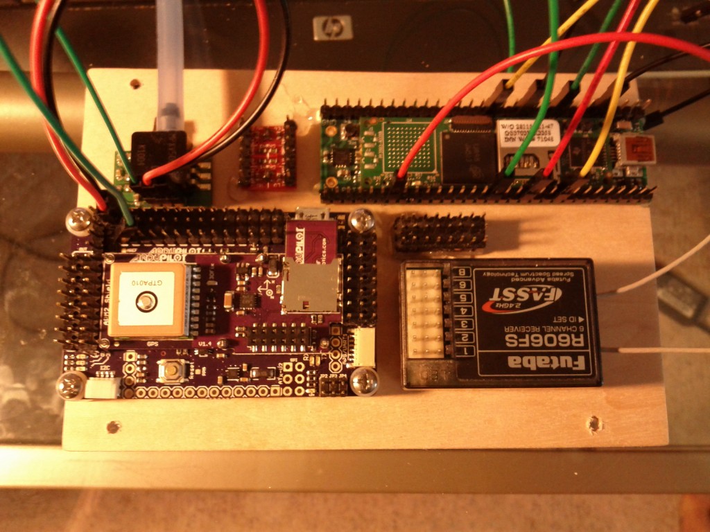
Here is a picture of a protype “hybrid” autopilot system for small UAV’s. What you see in the picture includes:
- An ArduPilot Mega 2.0 (lower left) The APM2 includes an MPU-6000 IMU, a Mediatek 5hz GPS, static pressure sensor, compass, and a variety of other items.
- A 1Ghz Gumstix Overo with a Pinto-TH expansion board. (longer thinner board, upper right). The Overo runs Linux, has 512Mb of RAM, and has a hardware floating point processor.
- An MPXV7002DP pressure sensor (upper left). This is attached to a pitot tube and measures airspeed.
- A Sparkfun TTL level translator (between the overo and the pressure sensor)
- A Futaba FASST 6 channel receiver (lower right)
- A set of power distribution rails (8×3 block of 0.1″ pins.)
- [not shown/mounted remotely] Digi Xtend 900Mhz radio modem.
The above picture was deliberately taken without most of the wires to show the components. Once all the wires are connected, things will look much more “busy”. This is a prototype system so the components will be jumpered together, probably with a bit of hot glue here and there to ultimately secure the wiring before flight.
Software Layout
Just as important as the hardware layout is the software layout. This is maybe a bit more boring and I can’t really take a picture of it to post here, but I will give a few bullet points for anyone who might be interested.
- The APM2 runs a custom built firmware that simply collects all the sensor data, packages it up into checksummed binary packets, and sends the data out over a uart. In addition, the APM2 reads checksummed binary packets inbound over the same uart. Generally inbound packets are actuator commands.
- The Overo runs a custom built autopilot application that is portable. It is not device/hardware independent, but it is designed to talk to a variety of hardware over a common interfaces. This Linux-based autopilot app can read all the sensor data from the APM2 (being transmitted at 100hz over a 500,000 baud link.) The autopilot app runs a computationally intensive 15-state kalman filter. Manages the mission tasks, computes wgs-84 great circle navigation targets, runs the low level PID code, and ultimately sends servo position commands back to the APM2 over the same 500,000 baud link.
- The high level autopilot software runs in an environment that is more natural and has more power/space for developing the “high concept” portions of the code. The APM2 is great for reading a bunch of sensors really quickly. In a hybrid system both major components are able to do what they do best without having to suffer through tasks they aren’t as good at.
- The high level autopilot is configurable through a structured XML configuration system. It includes an advanced 15-state kalman filter. It runs the same PID code configured in the same way as the FlightGear flight simulator. It also includes the same “property system” that FlightGear pioneered. It includes a rich set of IO API’s, and hopefully will soon sport a built in scripting engine.
- A word about the “property system”: The property system is an in-memory tree structure that relates “ascii” variable names to corresponding values. There is loose type checking and on-the-fly type conversion similar to many scripting systems (I can write a value as a ‘string’ and read it back out as a ‘double’ and the system does sensible conversions for me.) Any internal module can read/write the property tree, so it is a great way to build “loose” interfaces between modules. Modules simply reference the values they need and there is no compile time enforcement. This allows for building “robust” interfaces and eliminates much of the cascading changes throughout the code when a class gets updated. In addition, we can build external network interfaces to the property system which allows external scripts or other code to monitor and even modify the property tree. This allows external scripts access to the core values of the sim and access to set modes and otherwise “drive” what the autopilot does. In addition, there is a natural one-to-one mapping between the property tree and an xml config file. This is handy for easily loading/saving configurations. At a low level, property system variable access from the core code is simply a pointer dereference, so using these values is almost as fast as referencing a locally scoped variable. It is hard to describe in a few words what all the “property system” is or does, but it’s an amazing infrastructure tool that helps build flexible, robust, and high functioning code.
September 7, 2012 Update:
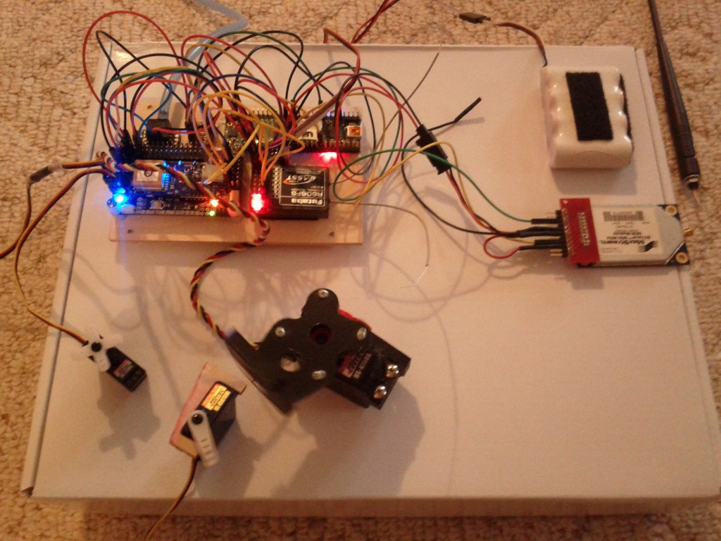
Here is a picture showing the whole system plugged together with 6″ sparkfun jumper wires. The wiring gets a little “busy” when everything is connected together so I plan to do some work buttoning things up, simplifying, and cleaning up the wire runs. I’ve attached 3 servos to test auto vs. manual outputs. You can see a 900Mhz Xtend modem (1 watt power, 115,200 baud), and the entire system is powered by a single RC receiver battery. In the aircraft this should all run just fine off the BEC. And here is a video of everything in action:
That’s about it. The modified APM2 firmware is happy and running. The overo autopilot code is up and running and talking to the APM2. Next up is validating the radio modem ground station connection, and then I’m running out of things to do before dropping this into an airplane!
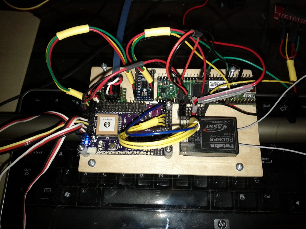
September 17, 2012 Update:
It’s far from a perfect integration, but I spent some time this evening bundling up wires. Definitely an improvement. Working towards full integration into a Senior Telemaster (electric powered) and hope to do some first test flights later this week. Today I test fit everything, powered everything from the main flight battery and verified basic control surface movements in manual mode and autopilot mode. The radio modem link is running and the mapping and instrument panel views on the ground link up and run.


