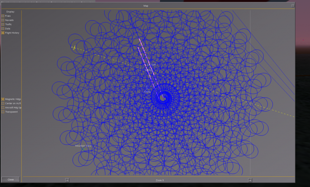
Spiraling Under Control
One of the staples of fixed wing autopilots is the circle hold. A circle hold is the closest thing you can get to a pause button with a vehicle that must be in constant forward motion to stay aloft. There are a few hidden challenges in the task, including wind compensation and some unexpected coupling that can lead to weird looking oscillations if not handled well. People have been doing circle holds with UAV’s for a long long time, so I don’t bring anything new to the table, but it is always fun to play, err I mean experiment.
Circles
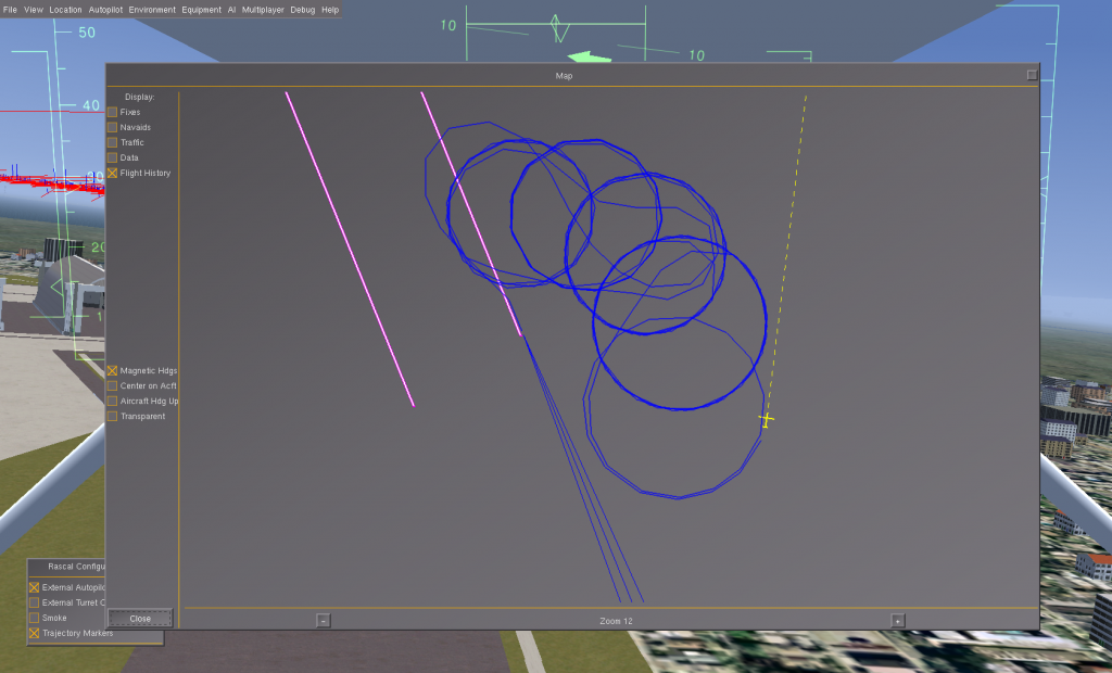
What happens if you periodically move the center of your circle (maybe every 5 mintues) to a new location, hold for a while, move the circle center again, circle for a while, and repeat? Well short answer is you end up with a bunch of circles, but if you are strategic in the placement of the circle center, some pretty patterns can begin to emerge. To add visual interest we can also change the circle speed when we move the center of the circle. Increasing the circling speed, increases the circle radius.
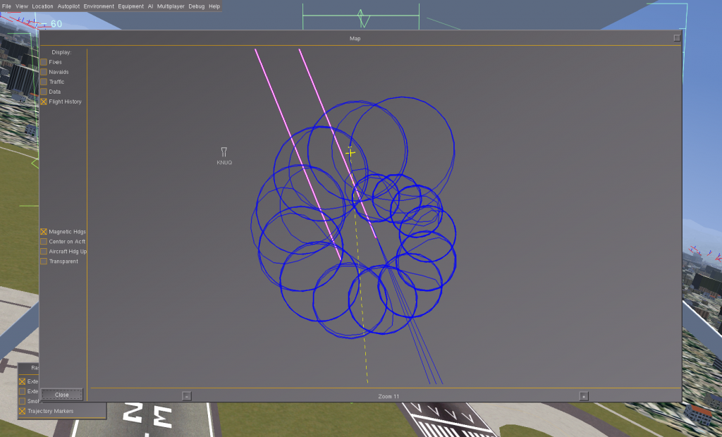
What if each time we move the circle center point, we move it by a fixed angle (let’s try 30 degrees), and increase the offset distance by a little bit, and also in crease the airspeed by a 1 kt? An interesting spiral pattern begins to emerge. From the original starting point, each circle is a bit bigger than the one before, and also a bit further away. A spiral pattern begins to emerge.
A flight simulator isn’t encumbered by battery or fuel limitations, so what happens if we let this run for a long time? The spiral pattern continues to develop and grow.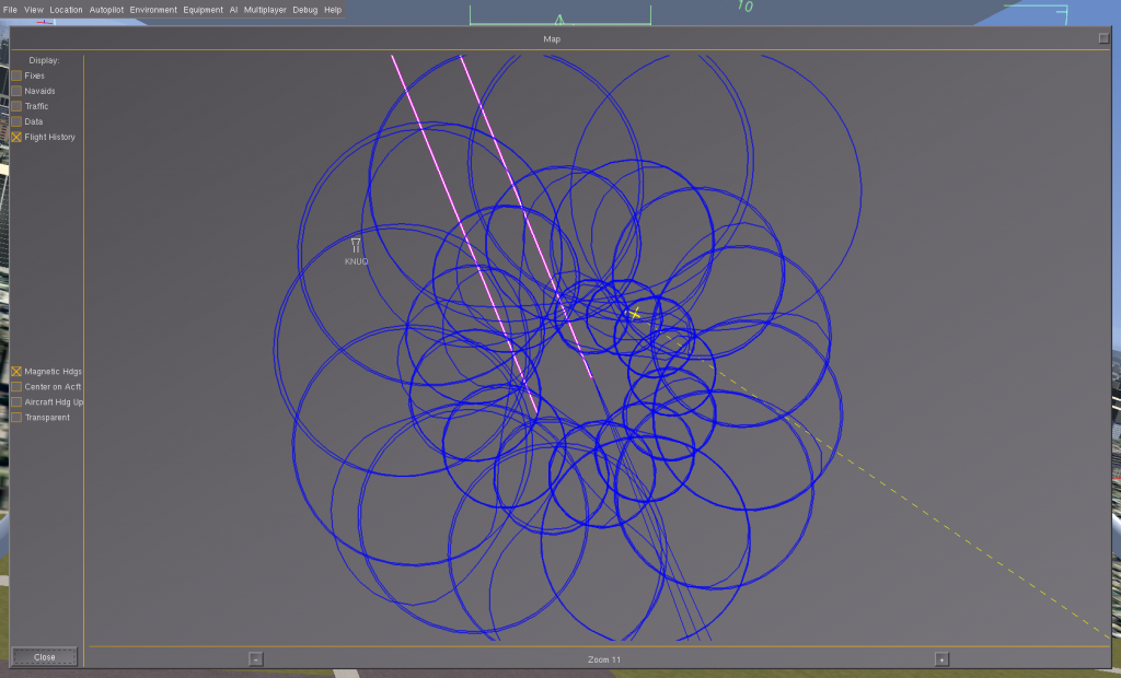
Spirals aren’t that big of a deal of course. 20 minutes of python coding could produce some far fancier spirals. What interests me is how the patterns are produced … this is the flight track of a simulated UAV and that makes it a bit more challenging and fun.
Continuous Spirals
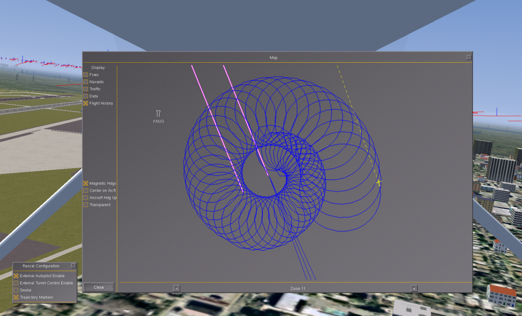
What happens if we fly a basic circle hold, but instead of changing the circle center point every 5 minutes, we continually move the center target of the circle in sweeping spiral pattern? We would get something that looks a bit like a stretched spring viewed from a bit of an angle.
At the beginning of the pattern, the airspeed is set to 25 kts. The radius (not of the circle hold but of the spiral) is set to 0.1 nm. Each second the position is swept forward 0.125 degrees. This means the spiral pattern sweeps forward 7.5 degrees per minute, or 450 degrees per hour. The airspeed and spiral radius are also increased by a tiny bit each second. The next picture shows the pattern after a bit more than an hour of flight.
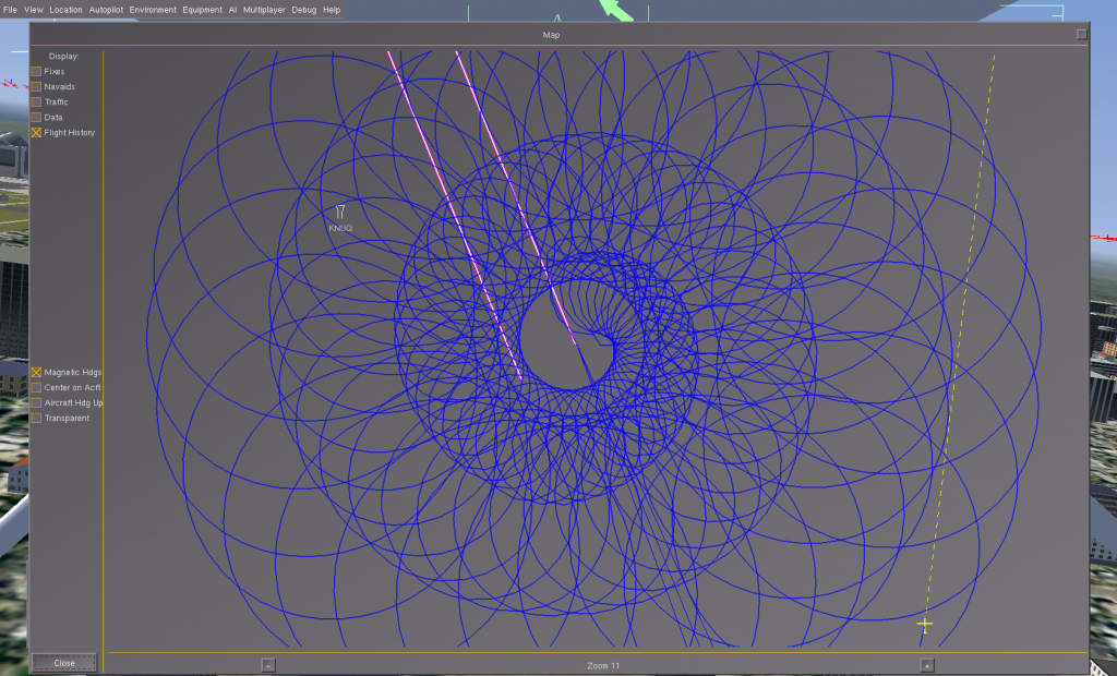
After about 5 hours of flight we get the next picture:
And if we let the simulation run over night and zoom out the map a couple steps, we get:
A Few More Details
All these patterns were produced by the flight track of a UAV. That means we aren’t just plotting mathematical functions, but instead are combatting wind and physics to produce these patterns. A complex system of sensors, attitude estimation, control theory, navigation and planning blends together to produce the end result.
Simulation vs. Reality
All of this was flown in the FlightGear.org flight simulator. However, there is a much stronger tie to reality than might first appear. FlightGear is the ‘stand in’ for reality. However all the sensor data is sent externally to the “avior” autopilot running in “software in the loop” testing mode. The avior autopilot code sends all the raw sensor information (simulated IMU and simulated GPS) into a 15 state kalman filter to estimate the actual roll, pitch, and yaw. It would be possible to cheat and use the simulators exact roll, pitch, and yaw, but the “avior” can’t cheat in real life (because this information isn’t directly available) so it faithfully estimates these values in simulation just like it must in the real aircraft.
The roll, pitch, & yaw estimates are then passed to flight control system and compared with target values for basic flight control and navigation. The “avior” autopilot computes control surface deflections to eliminate the error between target speed, and attitude vs. actual speed and attitude.
Finally, these control surface positions are sent back to FlightGear which then computes the flight physics based on where the avior moves the control surfaces and throttle. FlightGear computes new gyro, accelerometer, and gps sensor values, sends them to the avior autopilot, and the process repeats.
In this way we can test the “avior” autopilot quite thoroughly using the simulation. The avior thinks it’s really flying, it receives realistic sensor data, drives control surfaces as if they were real servos, and the simulator responds realistically. Really the only part of the avior not being thoroughly exercised is the specific code that reads the real world sensors and the specific code that drives the real world servos.
Wind
At first glance, the job of flying a circle hold around a fixed center point amounts to holding a fixed bank angle. There is a relationship between airspeed, bank angle, and turning radius, so we just need to work out these numbers and we can fly any circle of any radius at any speed, simply by computing the required bank angle.
But things get a bit more complicated than this because we need to adjust our actual heading and bank angle to compensate for drifting inside or outside the target circle radius. And there is this whole business of figuring out how to smoothly enter the circle pattern from any starting position and heading inside or outside the circle.
I’ll skip over the boring details (ask if you are curious) but along with all the other things that must be accounted for, the real world almost always has a little (or a lot) of wind. Flying up wind, small heading changes of the aircraft can yield large changes in your ground track heading. Imagine a worst case scenario where you are flying at 30 kts, exactly into a 30 kt head wind. You are hoving relative to the ground. But even the tiniest heading change (or wind change) will slide you 90 degrees left or right. The opposite happens when you are flying downwind. Aircraft heading changes produce proportionally smaller ground track heading changes.
Wind adds some unique challenges to flying circle holds that are actual circles from a ground perspective.
Coupling
I also wanted to say some brief words about coupling between axis, because it can be a bigger issue in circle holds than might first be expected. Imagine you are flying a perfect circle hold in zero wind. You are at a 30 degree bank, at your target airspeed, and at your target radius. Now imagine you are a bit outside of the target radius. You need to bank a bit more to tighten your turning radius. But this tighter bank could cause a loss of altitude (basic airplane physics). If the aircraft responds to the lost altitude with increased elevator, this will tighten your turn even more because you are banked. It is easy to over shoot and end up inside the circle, which means the flight controller will command the aircraft to fly less of a bank, increasing the circle radius, but that creates more lift, more climb, etc. Roll, pitch, and throttle can combine in some very awkward ways during a circle hold and that, along with wind and all the other aspects of basic aerodynamics and physics can make flying an accurate and stable circle hold a bit more of a challenge than you might first expect.
External Scripting
Hah, if you are still reading all the way down here, you are really a UAV geek (or you are following good skimming rules of reading the first paragraph, the last paragraph, and looking at the pictures.)
One of the fun things about the avior autopilot is that all the sensor data, attitude estimations, control surface positions, navigation state, and just about every other interesting variable is published in a giant hierarchical tree of name/value pairs. If you’ve poked inside the windows registery, it’s kind of the same basic idea, except all in memory and very fast to access or update.
The cool thing about this is that we can expose external interfaces to this giant data structure and completely command or monitor the autopilot externally. This enables a developer to write a perl or python script to monitor and command the autopilot. What sorts of things could such a script do?
- Command the autopilot to do a circle hold, then smoothly adjust the center point of the circle hold to produce interesting patterns in the UAV flight track. That’s what this whole article is about.
- Fly specific flight test maneuvers repeatably and accurately. Do you want to nail down the exact stall speed of your aircraft under different scenarios? You could write a script to fly the aircraft into a stall, then recover, climb to safe altitude, repeat. You could write scripts to put the aircraft into all kinds of different specific flight situations and carefully record the data. What is the elevator trim and power settings for level flight @ 25 kts, 30 kts, 35 kts, 40 kts, etc. How about at a 5 degree bank, 10 degree bank, etc.
- Create higher level intelligence without having to write code inside the core autopilot. The autopilot does everything for the aircraft, and it must be reliable and robust and never fail or do something dumb. This comes through long hours of flight testing. Now you want to go fiddle around under the hood and change something? That is begging for trouble! Why not leave the autopilot alone and write your new functions in an external script? Maybe you could write a fancy engine-out auto-land script that knows the basic performance characteristics of your aircraft and can plot and command an optimal approach path to touch down from any position and altitude to any landing strip in any wind conditions.
