How to be an Electronics Whiz on a Small Budget
Simple tools that you will use all the time!
I work with small electronics boards and components as part of my day job. I don’t really have a nice concise job title for myself, but lately it would be something like “UAS Embedded Flight Control Engineer”. I come from primarily a software / computer science background, but when you have an obstinate electronic gizmo sitting on your desk and no one to hold your hand, it’s time to get up to speed on some basic electrical engineering concepts.
Digital Multimeter
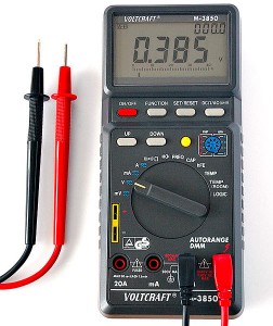
A digital multimeter is a great first tool. You can pick up one of these for a few bucks at home depot or just about anywhere. What can you do with one of these?
- Check the voltage of a pin or a trace or a through hole on your board. You can often learn a lot by checking the voltage at specific locations on your board. (This presumes some understanding of the components on your board and a schematic that shows how everything connects together.) Are you getting power where you should be getting power? If you have a little microcontroller running, is it driving the output pins high when it should? Driving them low when it should? There is a lot you can learn and debug and diagnose just by measuring voltages. Even when there is signal traffic across a line you can often deduce interesting information. For instance, the TX line on a serial port should live at +V (for whatever voltage you are running at) and the signal spikes should go low. The opposite happens for the RX line.
- Check if two points on your board are connected. My multimeter has a 2nd mode where it will ring out a continuous tone when I touch the two leads together or if I touch the leads to two ends of a wire or a trace. This can be really useful when you are hunting around a board and want to know where precisely the other end of a trace comes out, or verifying your solder joint is correct, or verifying you haven’t shorted something out, etc. This is very handy for basic troubleshooting and it’s amazing how much you can do with very simple tool if you understand your hardware and think carefully about what you are doing.
Oscilloscope
Normally we think of really high end test equipment that costs thousands of \($ when the word “oscilloscope” is mentioned. And I don’t doubt you get what you pay for in terms of capabilities and quality. But here’s an idea for the hobbiest who doesn’t have a couple spare thousands of\)$ in loose change they can dig out of their couch cushions on a moments notice: there are a ton of inexpensive oscilloscope modules you can buy that connect to your computer through the usb port and use your computer screen as the display. Many of these are in the $200 range — something that hobbiests could consider.
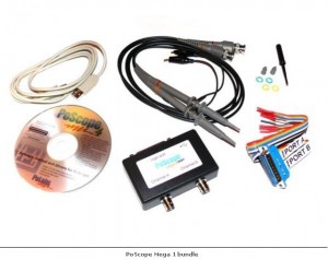
I poked around and decided to try the cheapest thing I could find: A “PoScope Mega1 Bundle” on sale for $162 at saelig.com. I don’t have any special allegiance to these guys, but they shipped right away and I have no complaints. Here’s what comes in the box. It may not look like much at first, but what you can do with it is pretty sweet, it’s a real oscilloscope after all.
Minor side note: The software you download to support this device is Windows only. I’m a Linux guy, but I have a Windows XP virtual machine running inside “Virtual Box” inside my Linux box. The best of both worlds for all you Hannah Montana fans. 🙂
There was a little slip of paper in the box directing me to go to www.poscope.com and download the latest software application and drivers. My bundle didn’t include one of those round shiny things which is just as well. After some fiddling around downloading and installing the drivers (and then rereading the instructions for installing the drivers and doing it again more carefully) I was up and running!
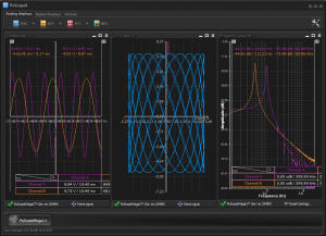
Here is a screen shot from the poscope page. It shows several things you can do. With two probes you can show two signals on a single plot. You can show the X, Y plot of the two signals, and even do some FFT frequency analysis of your signals.
This might sound like really complicated electrical engineering stuff, but let me bring it over to my world and show you some of the things I might like to use it for. The embedded electronics I deal with include microcontrollers that communicate with sensors and external pins. If something doesn’t work, sometimes it is important to get a little bit more detailed view of what’s going on besides looking at the steady state voltage or basic connectivity.
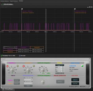
Here is a screen shot of serial communication traffic at 1.8v logic level:
- When two devices aren’t talking properly across their dedicated signal lines you can probe the communication at different points and see exactly what is happening. Is there signal traffic? What voltage level is the traffic at? Often different devices expect their digital signals to operate at different voltage levels. What if a 1.8v device needs to talk to a 3.3v device or a 5v device needs to talk to a 1.8v device? You need voltage level conversion chips and life gets a bit more complicated than you like … especially if something isn’t working. But with an oscilloscope you can probe different points of the communication path and see exactly what is happening. Is the source sending the signal? Is it being converted properly? Is the signal making it all the way to the destination?
- Digital logic analysis. The poscope includes a separate connector with 16 digital signal lines. The software includes a way to decode and display incoming serial traffic or other digital signals like i2c or spi communication. Are you trying to connect up an i2c or spi device and something isn’t quite working yet? Looking at the digital logic and relative timings of the different pulses might be just the thing you need to sort out exactly what’s going on.
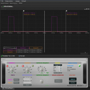
- I discovered another interesting use … debugging my code. I needed to write a small program for an ATTINY13A microcontroller. This is an 8-bit microcontroller running at 9.6Mhz. It offers a whopping 1k of flash for my programs, 64 bytes of internal SRAM, and all of 8 pins to receive ground/power, and talk to the outside world. There is no serial port for printf()’s, no display, no keyboard, no mouse. The programming device shares these 8 lines to upload new programs. Now to be fair, there is a whole suite of software you can download for windows, but I’m a linux guy remember, so what fun is that. I needed to validate clock timings and check if my interrupt service routine was responding correctly, so why not toggle one of the digital output pins, probe that with my oscope and validate the program operation and timing by measuring the pulse lengths of the digital signal that is being produced?
Conclusion
I’m barely scratching the surface of what you can do with an oscope (hey I’m learning as I go here too), but for < $200 why not consider picking up an inexpensive USB based oscilloscope. It may not be something use every day for the rest of your life, but on those days when you really need to see and understand a little bit more about what is happening on your circuit board or what your tiny microcontroller is really doing, an oscope is a great tool!
