What I want to do: Control RC Servos from a Gumstix Overo
I have a project where I need to drive standard RC servos from a Gumstix Overo. It doesn’t appear that the Overo ships with any built in PWM drivers. I did quite a bit of googling, and still couldn’t find a single drop-in driver that worked well for driving RC servos. I did find some great help though, rolled up my sleeves, and stitched pieces together to make the mother of all RC servo drivers.
The Overo has 4 available PWM signal generators on 4 specific GPIO lines. Scott provides a simple driver that demonstrates how to configure PWM10 to generate a signal at any frequency and duty cycle.
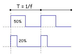
What is PWM? Frequency? Duty Cycle?
PWM stands for “pulse width modulation”. It is a common approach for computer servo control. Essentially the computer sends a short signal pulse (raises the signal line high.) The exact length of this pulse tells the servo where to position itself. The computer sends the pulse at a regular rate and varies the “width” (or the time span) of the pulse to control the position of the servo. This is how all standard RC servos work. The number of pulses we send per second is called the “frequency”. Typical RC systems use a frequency of 50hz. The ratio of the on versus off time of the signal is called the “duty cycle”. A duty cycle of 0% means no pulse at all. A duty cycle of 100% means the pulse is always on.

For a standard RC system running at 50hz, there will be a pulse generated every 20,000 us. (1 sec = 1,000,000 us; and 1,000,000us / 50hz = 20,000us). The pulse length to center a servo is 1500 us and the useful pulse range to run the servo through it’s full range of motion is about 1000 us – 2000 us. If you send a 1500us pulse every 20,000us, then the duty cycle is 1500 / 20,000 or 7.5%. The duty cycle range for controlling a servo at 50hz is then between 5% and 10%.
Scott Ellis’s “Basic” PWM Kernel Driver
Scott Ellis on the page linked above makes a basic pwm.c driver available. This driver only sets up one PWM (PWM10 aka GPIO145). This is routed to pin 28 on the “standard” 40 pin breakout header included on many overo expansion boards. This was a great start, but has some limitations.
- It only supports one PWM line (PWM10)
- Duty cycle is entered as an integer percentage. RC servos operate across the range of about 5-10% so that only gives me 6 unique positions, not nearly the granularity I want
Signal (Logic) Level Translation
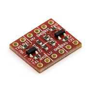
A quick note on something that can turn into a really tricky headache for newcomers to the Overo. The Overo uses 1.8v logic for all it’s output. This means that even though you are generating a perfect PWM signal to drive your servo, nothing will probably happen because the servo is expecting 3.3v (or maybe even 5v) signal logic. It may not see or respond correctly to 1.8v logic. This is also a more general issue for any external communication with the gumstix overo and is something embedded hardware engineers encounter every day. There are many ways to address this issue, but one quick and easy solution is to buy a logic level converter from sparkfun.com: http://www.sparkfun.com/products/8745

This sparkfun board supports level shifting for 4 lines at the same time. I soldered 0.1″ male header pins onto both sides and then used sparkfun 6″ single wire jumpers to connect things together. It is slick and relatively easy and with the color coded wires it even looks cool, especially on a glass desk with the office lights off and all the LED’s blinking. 🙂 All you have to do is tie your grounds together. Then connect 1.8v (pin #16 on the 40 pin header) to the LV side. Connect 3.3v (pin #2 on the 40 pin header) to the HV side, and then pipe the signal line through to the servo. Despite the RX/TX labelling, I believe the signal conversion is bi-directional on the latest version of this sparkfun level shifter board.
Jack Elston’s Driver Extension to Support all Four PWM Lines
Scott emailed me an update to his pwm.c which expands support to all 4 hardware PWM signal generators. This is a great next step. However this version of the driver also had some limitations:
- PWM10 and PWM11 used the 32Khz clock (which is the default). Leaving the details aside, the 32Khz clock can only achieve about 32 unique positions across the typical RC servo range of motion.
- I believe there is some integer overflow for PWM8 and PWM9 when computing the duty cycle which leads to odd results.
- Part way into the project I decided I wanted to generate PWM pulses with sub us resolution.
13Mhz Versus 32Ghz Clock
Scott Ellis to the rescue again. Scott emailed me an older testing driver he had built called “pulse.c” (note: Scott makes all his drivers available github.com under the GPL license.) The pulse.c driver includes code to set the PWM10 and PWM11 timers to use the 13Mhz clock.
The 13Mhz clock allows us to have 259,998 duty cycle steps. In other words 0 corresponds to 0% duty cycle and 259,998 corresponds to a 100% duty cycle. Since an RC servo is expecting a 5-10% duty cycle at 50hz, this gives us a numeric range of about 13,000 values to work with. We are interested in a pulse with range of 1000-2000us (a range of 1000us) so 1000us / 13,000 step sizes gives us better than 0.1us resolution.
0.1 us resolution gives us 10,000 unique positions across the range of motion of a typical RC servo. For reference, if we were driving a pan servo on a camera system that was setup for 180 degree coverage, we would have approximately 0.02 degree resolution.
Now, whether or not an RC servo can resolve input signals down to this level of accuracy is a different discussion, but servo technology does continue to improve steadily.
Integer Overflow!
Integer overflow is never any fun. The math proceeds without reporting any errors and you get the wrong answer. Grrr. Note that INT_MAX for an unsigned 32bit integer is 4294967295. tmar is the integer duty cycle percentage ranging from 0 to 259,998. num_freq is the max number of duty cycle steps (in our case 259,998 for the 13Mhz clock.) The formula to compute the tmar value is then: pulse_us * frequency * num_freq / 1000000.
Here’s the problem, when computing this formula with a pulse of 1500us, you get an intermediate value of 19499850000 before dividing by 1,000,000. This is way larger than INT_MAX so the math wraps around and the result after the divide is totally wrong.
As a work around I observe that frequency (50) divides evenly into 1,000,000 so I can rearrange terms and do that division first. This keeps all the intermediate values less than INT_MAX.
Getting to 0.1 us Resolution
So far so good if I’m specifying integer us pulse widths to the kernel. However I want to have 0.1 us resolution because the 13Mhz clock offers that level of resolution.
Doing floating point math inside a kernel driver is considered bad form, and you have to do a lot of horsing around just to get proper machine code generated and linked with the right libraries. We don’t want to go there, so no floating point.
Instead I will specify timing values in 10ths of a us. So to request a 1500us pulse I would write a value of 1500us*10 or 15,000. Writing a value of 15,001 to the driver will give me a 1500.1 us pulse.
Back to integer overflow again. Specifying a larger input value in the range of 10,000 to 20,000 suddenly pushes me back into integer overflow territory with my intermediate values. 259,998 / INT_MAX = 16519.2 so any pulse longer that 1651.9 us will push me back into int overflow. The solution is that I observe that 259,998 is divisible by 2, so I can pre-divide this number by 2 and earlier divide 1,000,000 by 2 to get an equivalent answer. This allows me to specify signal widths of up to 3303.8 us which is well beyond that standard RC range again. I realize this is a pretty specific solution for this particular hardware and this particular clock frequency, but when dealing with embedded systems, you often have to get specific.
What’s so special about 259,998?
When dealing with low level hardware and clocks, you end up running into very odd ball numbers that some CPU hardware designer somewhere must have thought was cool. 259,998 is an annoying number. Prime factorization is 2 • 3 • 17 • 2,549. This means it’s hard to divide evenly with anything and it can be a challenge to try to simplify integer math expressions to eliminate intermediate integer overflow!
Observe that 259,998 * 50hz = 12,999,900. In computers, kilo often refers to 1000 and mega refers to 1,000,000. So 12,999,900 / 1,000,000 = 12.9999 Mhz. Let’s round that up to 13 and I think you see this is the number of clock ticks per second a 13Mhz clock generates. 259,998 is the number of ticks per 1/50 of a second. (You see, it all makes perfect sense!)
Getting the Updated Driver Code (Driver to Command and Control 4 High Resolution PWM Signals on a Gumstix Overo)
Future Enhancements
Scott suggested that a nice extension would be to allow the user to select which of the 4 PWM channels are activated and configured when the module is loaded (or via a platform device whatever that is.)

