Better FlightGear Smoke
Overview
A popular way to create smoke effects in visual simulation is through particle systems. Briefly, a particle system emits particles. Each particle can have a texture as well as a variety of physical characteristics. Particles can be shot or just placed in the world. If you shoot your particles you can control a randomize range of angles and speeds. You can give your particles a life span in seconds and have them grow or shrink over their life. Particles can have mass and surface area which affects their motion. They can move relative to the world or relative to the shooter. They can blow in the wind, they can spin in various axis; there are many cool things you can do with particles!
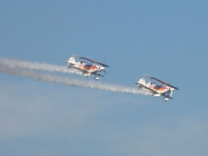
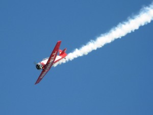
I am going to focus on a smoke trail emitted by an aircraft engine. Often, aerobatic aircraft are rigged to dump a special oil into the hot engine exhaust which creates a thick smoke trail. This is really cool at air shows.
We would like to simulate this effect in FlightGear and we do. However, I’m a little unsatisfied with some of the existing particle configurations. I’ve seen much better in other packages. I have carefully made some improvements which I will explain here. Hopefully other aircraft developers can take this and run with it and make their smoke effects look even better.
Example
For detailed documentation on the FlightGear particle system, please consult the file README.xmlparticles in the FlightGear documentation folder (included with every installation.) Here is an example xml config file I have been working with to create smoke effects for my small UAV models:
<particlesystem>
    <name>smoke</name>

    <offsets>
      <x-m>  0.000 </x-m>
      <y-m>  0.000 </y-m>
      <z-m>  0.000 </z-m>
      <roll-deg>    0.000 </roll-deg>
      <pitch-deg>   0.000 </pitch-deg>
      <heading-deg> 0.000 </heading-deg>
    </offsets>

    <texture>smoke.png</texture>

    <condition>
      <property>sim/multiplay/generic/int[0]</property>
    </condition>

    <emissive>false</emissive>
    <lighting>false</lighting>
    <align>billboard</align>
    <attach>world</attach>


    <placer>
      <type>point</type>


    </placer>

    <shooter>
      <theta-min-deg>70</theta-min-deg>
      <theta-max-deg>110</theta-max-deg>
      <phi-min-deg>70</phi-min-deg>
      <phi-max-deg>110</phi-max-deg>
      <speed-mps>
        <value>10</value>
        <spread>5</spread>
      </speed-mps>
      <rotation-speed>
        <x-min-deg-sec>0</x-min-deg-sec>
        <y-min-deg-sec>0</y-min-deg-sec>
        <z-min-deg-sec>-180</z-min-deg-sec>
        <x-max-deg-sec>0</x-max-deg-sec>
        <y-max-deg-sec>0</y-max-deg-sec>
        <z-max-deg-sec>180</z-max-deg-sec>
      </rotation-speed>
    </shooter>

    <counter>
      <particles-per-sec>
        <value>200</value>
        <spread>5</spread>
      </particles-per-sec>
    </counter>

    <particle>
      <start>
        <color>
          <red><value>   1.0 </value></red>
          <green><value> 1.0 </value></green>
          <blue><value>  1.0 </value></blue>
          <alpha><value> 0.3 </value></alpha>
        </color>
        <size>
          <value>0.2</value>
        </size>
      </start>

      <end>
        <color>
          <red><value>   0.95  </value></red>
          <green><value> 0.95  </value></green>
          <blue><value>  0.95  </value></blue>
          <alpha><value> 0.001 </value></alpha>
        </color>
        <size>
          <value>5.0</value>
        </size>
      </end>

      <life-sec>
        <value>30</value>
      </life-sec>

      <mass-kg>0.1</mass-kg>
      <radius-m>0.25</radius-m>
    </particle>

    <program>
      <fluid>air</fluid>


      <gravity>false</gravity>
      <wind>true</wind>
    </program>

  </particlesystem>
Again, rather than explain everything in detail, I just want to touch on several items that perhaps are being misunderstood or overlooked.
- Shooter theta and phi: These values control the range of angle that particles are shot from the emitter. It is important to notice that these angles are specified in degrees. A theta value of 0 degrees is straight up and a phi value of the 0 degrees is out the right hand wing. So if you want your particles to be emitted straight out the back, you want both phi and theta to be 90 degrees. However the smoke gets mixed up in the wake turbulence coming off the aircraft so the puffs go in different directions. In this example I’ve set a max/min range for both theta and phi of 70 to 110 degrees. This is +/- 20 degrees from straight out the back.
Update: May 12, 2011: The phi/theta values actually depend on your overall model orientation. I recommend you setup a positive shooter speed, zero wind, and then play with these numbers when the model is sitting on the ground to make sure you have the angles and orientations correct. - Shooter speed: Smoke quickly mixes with the atmosphere and blows with the prevailing wind, so shooting the smoke at a particular speed is not too important. However, in terms of creating some randomization to the smoke trail it does help to shoot the initial puffs in a variety of directions and speeds.
- Rotation speed: This is a very important one that I’ve seen misused in several configurations. Notice that particles are billboarded so they always face the viewer. If you look at a “sprite” edge on, you see it’s flatness and that doesn’t look right. We do want some rotation though, this gives the effect of the swirling vortexes coming off the wing tips and tail of an aircraft. As the smoke gets mixed up in the air currents, you can visually see it spin in real life. Here is the critical thing to notice: if you give any rotation in x and y, you will be tumbling the surface that the particle image is drawn on and the viewer will see the edge on sprite and it won’t look right. However if you rotate in the z axis, you get what you want, a sprite that always faces the viewer but spins either clockwise or counter clockwise depending on the spin rate you specify. In this example I use +/- 180 deg/sec which seems to work pretty well.
- Counter particles-per-sec: Another thing I played with was how many particles per second are emitted. You need to to balance the particle size with the number emitted against your computer graphics speed to try to come up with a realistic smoke trail. Ideally you would use lots of smaller particles, but this can affect render speeds. So you might want to increase the size of the particles and then generate them at a slower rate. You can also control the lifespan of your particles so shortening that up is another way to reduce graphics load.
- Particle start and end size: You can can specify a starting size of the particle and an ending size of the particle. You also specify the life-span of the particle, so it will grow linearly to the ending size over the course of it’s life. This is important with smoke effects because if you focus on a single point in a smoke trail, you will see the smoke expand and then dissipate. We can simulate this by making our particles grow over time.
- Particle physics: You can specify the mass of each particle as well as it’s radius. These numbers do not affect the size as it’s drawn on screen, but do affect the motion of the particles. If you create a very light particle (0.001kg) with a large radius (1m) then it doesn’t matter what direction or how fast you shoot the particle, it will immediately follow the local airmass. The problem with this is that you get a very uniform smoke trail with no variation at all. If you increase the mass (1kg) and decrease the radius (0.1m) suddenly your smoke particles start acting like rubber balls and they shoot out in a scatter pattern. So the trick is to find the right balance of mass and radius so that your particles scatter a bit to simulate turbulent air behind the aircraft, but not too much and not too little. The numbers I came up with were mass = 0.1kg and radius=0.25m.
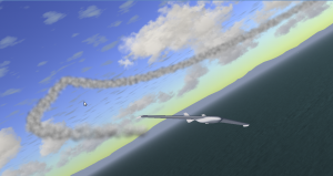
- Texture: One other important thing to mention is the texture. You have control over the texture that gets drawn for each puff (particle) of smoke. There are example textures you can copy from other aircraft or you could make your own. Generally I like smoke/cloud textures that are all white, and vary only in transparency. However, for smoke particles, giving a little shading on your particle bitmap might look nice and give a bit more variation to the smoke trail. Also it will help show off the spinning vortexes a bit better. As you can see in my screenshots, the current smoke texture is probably a bit too dark in places — yet another thing to try to balance into the overall effect.
I think I have taken several significant strides forward to create a better smoke trail configuration for FlightGear, however, I’ve still seen better in other software packages. This is something I will continue to work on and hopefully other developers will pick up on too, now that they know exactly what parameters they need to tune and why.
UAS Visualation
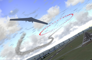
Smoke trails and trajectory markers can be two great tools when prototyping and developing UAS flight control systems. Trajectory markers show the absolute flight path in world coordinates, and a smoke trail shows the relative path in the air mass. Turn them both on at the same time to see how they relate to each other. This enables an engineer to see exactly what their aircraft is doing under a variety of wind and turbulence conditions.


