Python Airfoil Manipulation Library
For lack of a better title …
I am creating a set of python libraries for designing and modeling aircraft. Rather than spend a couple months learning a complicated and expensive CAD tool, why not spend that time learning python? It makes perfect sense to me. 🙂
Scripted modeling (versus interactive point and click modeling) is a different mind set, but the advantage is you can make a change to the script and rerun it and that change cascades through all the parts and drawings and layout sheets. In a gui based CAD system if you need to change the radius of an alignment hole that runs through all your wing ribs, you might have to painstakingly edit each and every rib, right? What if you want to move a stringer, or add an lightening hole, or increase the wing chord by 10%? Those can be daunting tasks in a typical cad system. But in a scripted modeling system you may just need to change a number, or add a couple lines of code, and rerun the script and you are done.
Here are a few pictures to illustrate the sorts of things I am up to. If you are a model builder I think you will immediately see what is going on. Please click on the illustration for larger fully detailed versions.
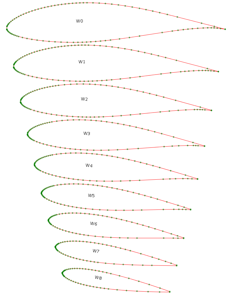
The following image shows blending two different airfoils: NACA 63(3)618 into NACA0015. Also shown is the ability size the airfoil to any scale and rotate it to any angle of incidence.
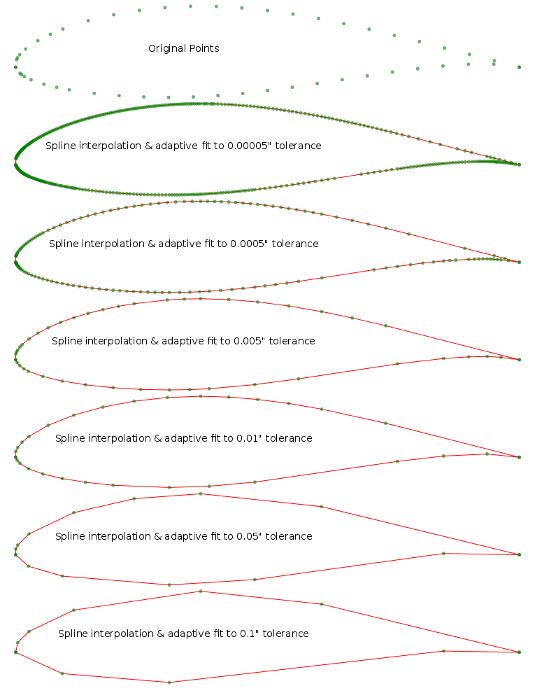
The next image shows (1) the ability to read in a standard airfoil plot, (2) fit a smooth spline interpolation through the original data set, (3) resample the airfoil at any resolution and step size, and (4) do an adaptive fit of the higher resolution data that conforms to a specific error tolerance. Data reduction and fitting can be important for to keep file sizes from growing too large and for reducing cut times.
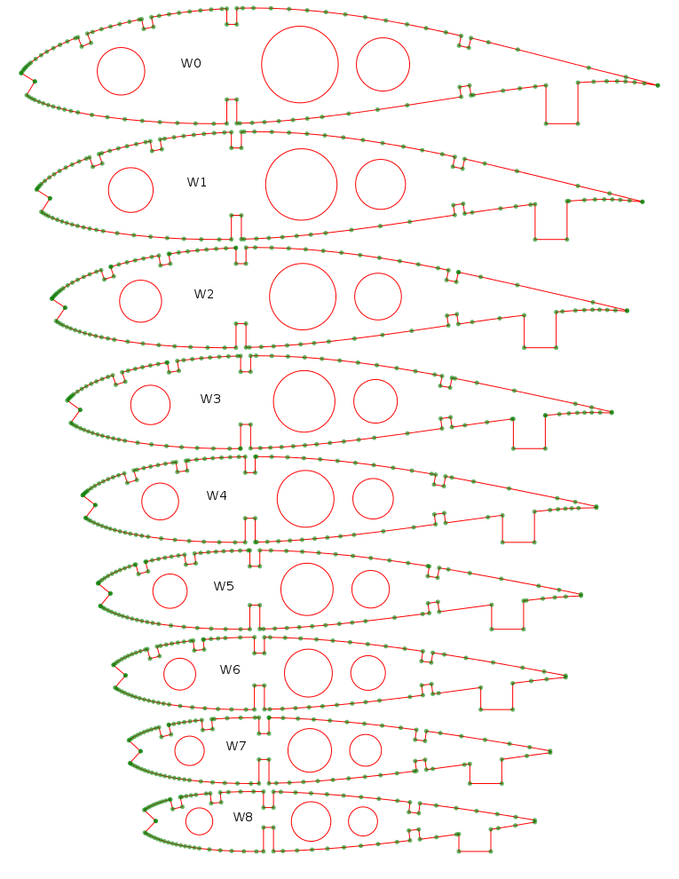
The final image shows features that are important to modelers. The ability to cut in spars of any width and height that are flush with either the top or the bottom. The ability to cut out stringers that are either vertical or tangent to the surface of the airfoil. The ability to cut out a leading edge diamond and automatically orient it for the best fit and minimal sanding. And finally the ability to cut lightening holes and add build alignment tabs.
Another capability the library currently has (not shown in the illustrations) is the ability to skin an airfoil by some width. The library will shave off that amount in a sweeping arc that follows the original contour of the airfoil. This would be appropriate (for example) if you planned to sheet your wing with 1/16″ balsa. You can shave off that 1/16″ from the ribs so that when you do the final sheeting, you will be back to the exact airfoil dimensions you intended. You can also shave off portions of the airfoil if you plan to only sheet a part of the wing and leave part of it as an open framework.
If you are curious what the python code to create these images looks like, you can go to the links below, but for example here are some basic lines of code you can add to your script:
Load an airfoil, do a smooth spline interpolation, and resample it at 1000 steps:
root = airfoil.Airfoil("naca633618", 1000, True)
Blend two different airfoils together with some weighted percentage:
rib = airfoil.blend( root, tip, percent )
Add a lightening hole at a specific location and radius:
rib.add_hole( hx, hy, hr)
Next up: the next major component of this system that I hope to tackle is laying out the top down plans of the wing. The output would be an svg (or pdf) file that you could send to a large format plotter and print out the exact wing plan for construction.
If you are interested in taking a closer look at this project, I have setup a git repository with all the code and demos at the following link:
The project README file (which includes quite a bit more background and details) can be read here: